Maintenance 5-243
Replacing Internal Components
Tools Required
The following tools are required for this procedure:
• 3/16-inch flat-blade screwdriver to remove the chassis top front panel.
• Long (12 inches or longer) 3-mm center hex Allen-head wrench or driver for the captive screws
on the blower. (A T-handle driver is included with blower spares kits.)
• Flashlight (optional).
Although the far left Allen-head screw on the blower is slightly obscured from view by the left lip
of the chassis and the left blower air duct, an access hole in the lip of the chassis is provided
specifically for access to this screw. By inserting the Allen wrench straight into the access hole, you
should be able to find the screw without any trouble. However, if you do have trouble finding the
screw, and if the lighting around the chassis is poor, you may need a flashlight to locate the screw
and position the Allen wrench correctly.
Removing the Blower
Remove the existing chassis blower as follows:
Step 1 On each installed power supply, turn OFF the power switch and unplug the power cable
from the power source.
Step 2 Remove the front panels according to the procedure in the section “Removing and
Replacing the Front Chassis Panels” earlier in this chapter.
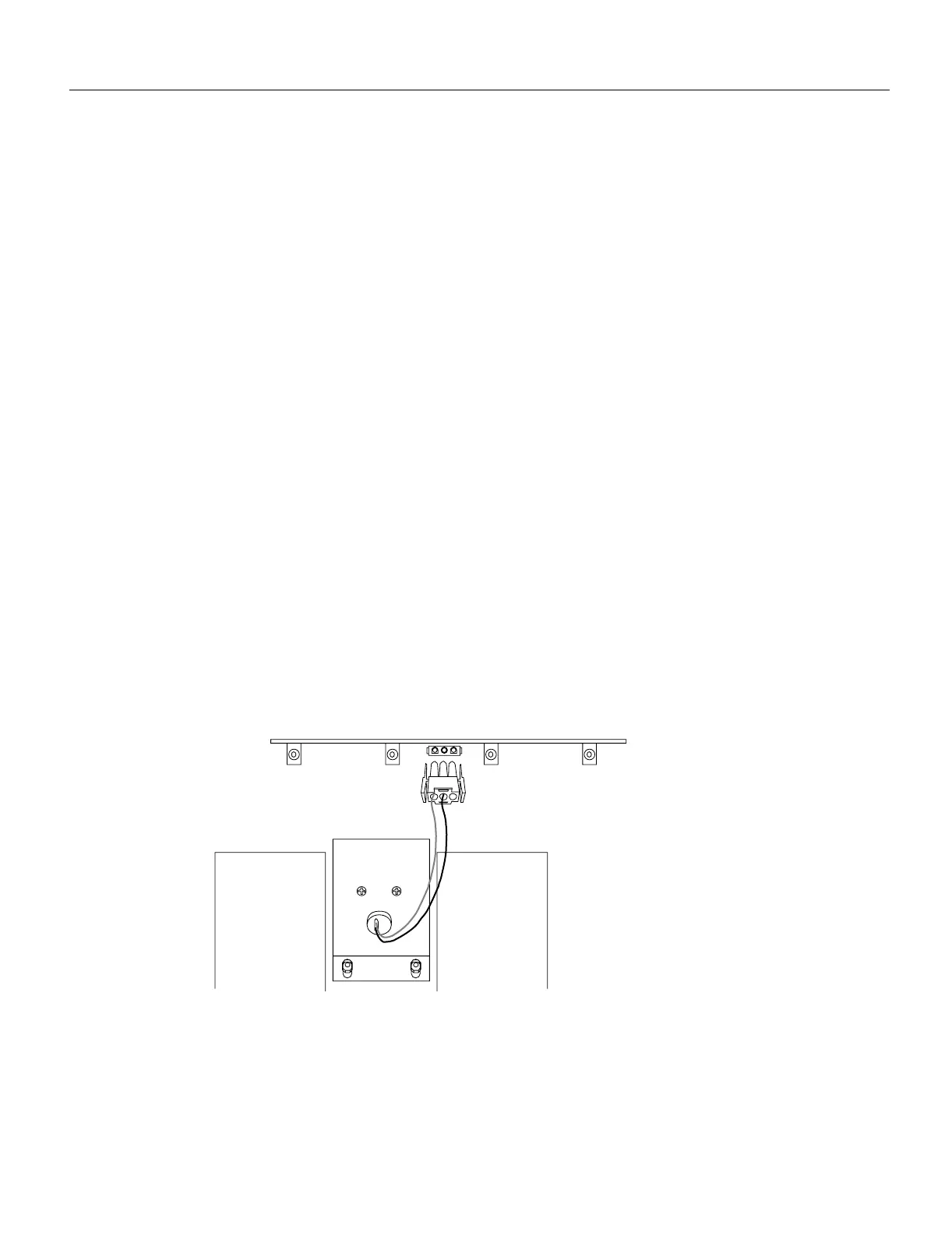
Step 3 Locate the blower (see Figure 5-30), which is mounted to the bottom of the backplane, and
the blower power connector (see Figure 5-33), which is connected to a port in backplane
under the white power bar. Note the orientation of the blower power connector and its
orientation in the backplane port.
Figure 5-33 Blower Power Connector
Step 4
Disconnect the blower 24 VDC power connector from the backplane by pinching the sides
of the connector inward and pulling the connector out and away from the backplane. Lay
the connector and wiring on top of the blower to keep it out of the way while you remove
the blower.
Black (ground)
Purple (+24V)
Blower
H1385a
Blower power connection
Backplane

 Loading...


