1-26 Cisco 7000 Hardware Installation and Maintenance
Physical Description
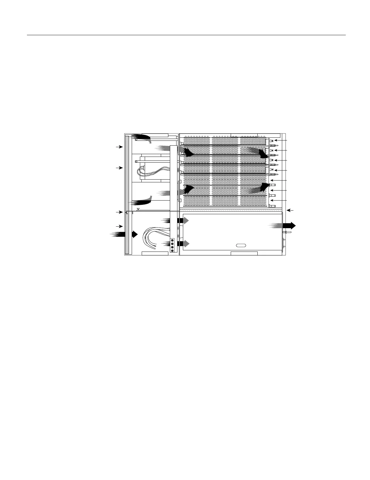
System Blower
The system blower provides cooling air for the RP, SP (or SSP), and interface processors. The blower
is located inside the front chassis compartment as shown in Figure 1-7.
An internal fan in each power supply draws cooling air from the front of the chassis, through the
power supply, and out the back of the chassis. (See Figure 1-7.) An air dam keeps the power-supply
airflow separate from that of the rest of the chassis (which is cooled by the system blower).
Figure 1-7 Internal Airflow, Top-Down View
The blower draws air in through the air filter in the front chassis panel and directs it up through the
floor of the internal slot compartment and over the boards. The exhaust air is forced out the rear of
the chassis above and to each side of the processor slots. Figure 1-7 shows the airflow path. The
blower needs a clean air filter in order to draw in sufficient amounts of cooling air; excessive dust in
the filter will restrict the airflow. Keep the air filter clean and replace it when needed. The
“Maintenance” chapter provides air filter cleaning and replacement procedures.
Sensors on the RP monitor the inlet and internal chassis air temperatures. If the air temperature at
either of the sensors exceeds a desired threshold, the environmental monitor displays warning
messages and can interrupt system operation to protect the system components from possible
damage from excessive heat or electrical current. For specific threshold and status level descriptions,
refer to the section “Environmental Monitoring and Reporting Functions” in this chapter.
Route Processor (RP)
The RP, shown in Figure 1-8, is the main system processor in the router and is installed in the far
right card slot labeled RP. The RP contains the system central processing unit (CPU), the system
software, and most of the system memory components, and it maintains and executes the
management functions that control the system. The RP contains the following components:
• 25-MHz Motorola MC68040 CPU for processing key functions that are not time-critical
• System hardware configuration register for setting default boot instructions
• Bank of hardware (MAC-layer) addresses for the interface ports
H1338a
Power
supplies
Front of
chassis
Rear of
chassis
Air dam
Slot
0
1
2
3
4
SP
or
SSP
RP
Air dam
System blower
Air duct
Air duct

 Loading...


