Installing the Router 3-121
Installing Power Supplies
Step 11 Secure each ear to the rack-mounting strip with two 10-32 x 3/8-inch slotted binder-head
screws.
Step 12 Proceed to the section “Connecting AC and DC Power” later in this chapter.
Inserting Power Supplies
When you have clear access to the power supply bays, install the first AC-input or DC-input supply
in the lower bay and the second supply, if any, in the upper bay. Each power supply weighs 20
pounds. Figure 3-2 shows the correct way to handle a power supply. Install each power supply as
follows:
Step 1 Always install the first power supply in the lower bay. If a filler plate is installed on the
lower bay, use a screwdriver to loosen the captive screw and remove the plate. Store the
filler plate in a safe place; you should replace it whenever a power supply is not installed in
the bay.
Step 2 Check the switch on the face of the power supply, and place it in the off (O) position. The
interlock tab should not extend out of the unit.
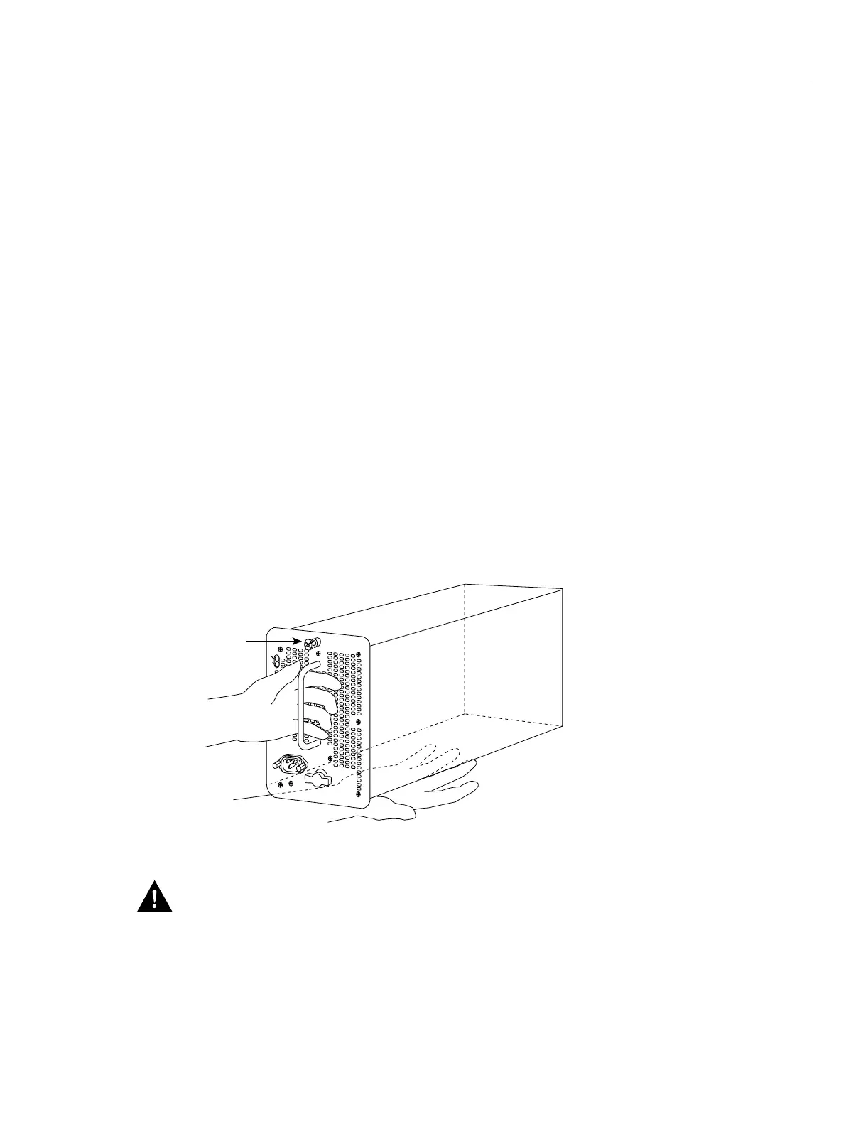
Step 3 Hold the power supply by the handle and place your other hand underneath to support the
bottom. (See Figure 3-2.)
Step 4 The power supply has casters on the bottom end. Place the casters inside the lower power
supply slot and position the power supply so that it is aligned in the slot to go straight in.
Figure 3-2 Handling Power Supplies—AC-Input Power Supply Shown
Caution
When inserting a power supply into the bay, do not use unnecessary force; slamming the
power supply into the bay can damage the connectors on the rear of the supply and inside the chassis.
Step 5 Push the power supply all the way into the bay. Do not use unnecessary force; push the
supply into the bay until the power supply front panel is flush with the chassis rear panel.
Step 6 Tighten the captive installation screw on the top of the power supply. This screw prevents
the power supply from shifting away from the internal connector and provides proper
grounding for the supply.
I
0
DC FAIL
AC POWER
H1356a
Captive
installation
screw

 Loading...


