2-102 Cisco 7000 Hardware Installation and Maintenance
Preparing Network Connections
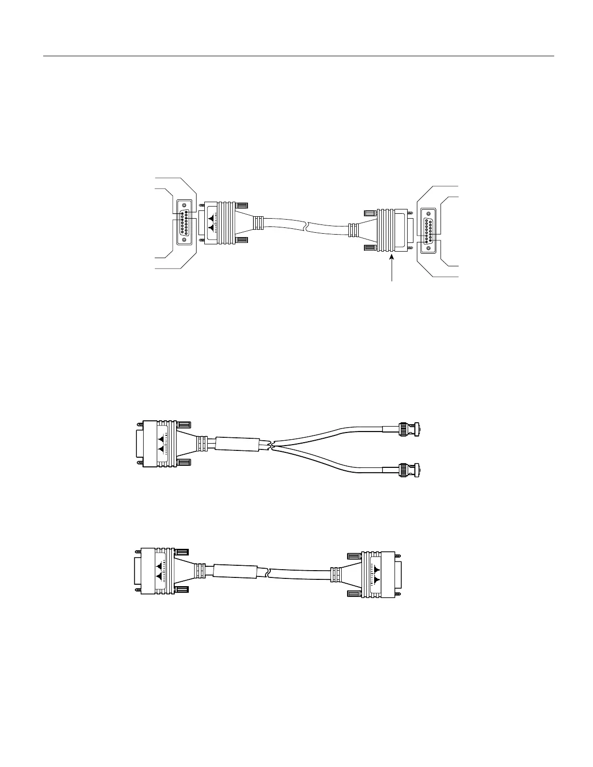
MultiChannel (MIP) Connection Equipment
The MIP T1 interface cable has two 15-pin DB connectors at each end to connect the MIP with the
external T1 CSU. Figure 2-26 shows the MIP interface cable, connectors and pin-outs.
Figure 2-26 MIP Interface Cable Connector
For E1, four serial cables are available from Cisco Systems for use with the MIP. All three have
DB-15 connectors on the MIP end and either BNC, DB-15, Twinax, or RJ-45 connectors on the
network end. Figure 2-27, Figure 2-28, Figure 2-29, and Figure 2-30 show the E1 interface cables
(respectively).
Figure 2-27 E1 Interface Cable for 75-Ohm, Unbalanced Connections
(with BNC Connectors)
Figure 2-28 E1 Interface Cable for 120-Ohm, Balanced Connections
(with DB-15 Connectors)
Pin 1
Pin 9
Pin 11
Pin 3
Pin 1
Pin 9
Pin 11
Pin 3
72-XXXX-01
MIP
T1 or null-modem
connector (typical)
H2385
H2421
H2476

 Loading...


