EasyManuals Logo

Cisco 7000 Hardware Installation And Maintenance

Cisco 7000
319 pages
To Next Page IconTo Next Page
To Previous Page IconTo Previous Page
Page #243 background imageLoading...
Page #243 background image
Maintenance 5-239
Replacing Internal Components
Tools Required
You need a number 1 Phillips or 3/16-inch flat-blade screwdriver to remove the top front chassis
panel.
Warning Before accessing the chassis interior, turn the system power OFF and unplug the power
cord. The backplane carries high voltages when the system is operating.
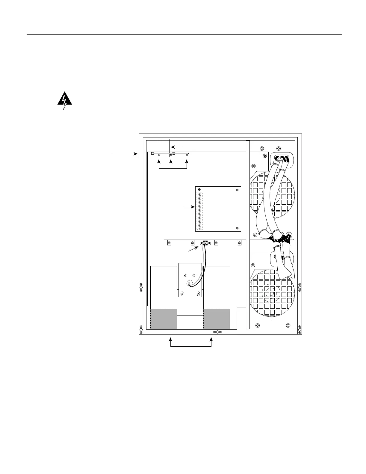
Figure 5-30 Internal Chassis Components
H1334a
LED board
(mounted on horizontal
plane in chassis)
LED board spring
LEDs
Arbiter board
connector
Blower power
connection
Blower air ducts to
interface processor
compartment

Table of Contents

Other manuals for Cisco 7000

Questions and Answers:

Question and Answer IconNeed help?

Do you have a question about the Cisco 7000 and is the answer not in the manual?

Cisco 7000 Specifications

General IconGeneral
Product TypeSwitch
Model7000
CategorySwitch
PortsVaries by configuration
Power SupplyRedundant power supplies supported
ManagementSNMP, CLI

Related product manuals