5-240 Cisco 7000 Hardware Installation and Maintenance
Replacing Internal Components
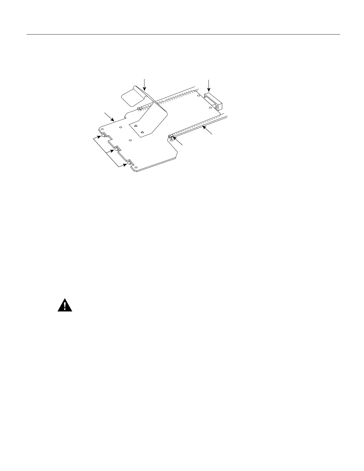
Figure 5-31 LED Board
Removing the LED Board
Remove the existing LED board as follows:
Step 1 On each installed power supply, turn OFF the power switch and unplug the power cord from
the AC source.
Step 2 Remove the front panels according to the procedure in the section “Removing and
Replacing the Front Chassis Panels” earlier in this chapter.
Step 3 Locate the LED board (see Figure 5-30), which is mounted on a horizontal plane in two
plastic brackets.
Step 4 Two steel pins near the front of the brackets hold the board in place. (See Figure 5-31.) On
each pin, place your thumb on the top of the pin and your forefinger underneath the bracket
to support it, and press the pins down and out of the guide holes in the board.
Caution Handle the LED board by the edges only to avoid damage from ESD.
Step 5 Grasp the edges of the board and place a finger on the top of the LED board spring to
depress it.
Step 6 Keep the spring depressed as you pull the board straight out at a 90-degree orientation to
the backplane.
Step 7 Place the board in an antistatic bag if returning it to the factory.
H1387a
LED board
brackets
Board locking
pin
LED board
spring
Backplane connector
LEDs
LED board

 Loading...


