Preparing for Installation 2-101
Preparing Network Connections
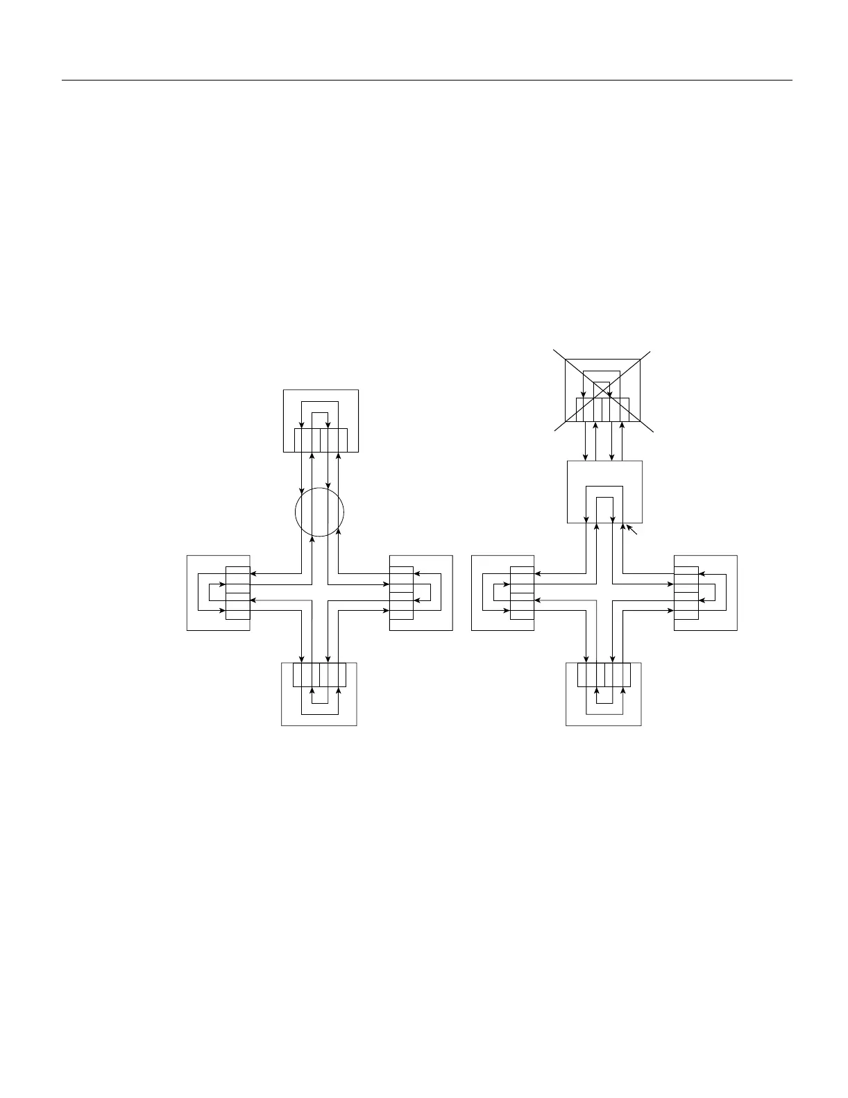
Optical bypass switches avoid segmentation by eliminating failed stations from the ring. During
normal operation, an optical bypass switch allows the light signal to pass directly through itself
uninterrupted. When a station with a bypass switch fails, the bypass switch reroutes the signal back
onto the ring before it reaches the failed station, so the ring does not have to wrap back on itself.
Figure 2-25 shows an optical bypass switch installed at Station 1. In the normal configuration shown
on the left of the figure, Station 1 is functioning normally, so the optical bypass switch appears
transparent. The switch essentially allows the signals to pass through it without interruption.
However, if Station 1 fails, the optical bypass switch enables the bypassed configuration shown on
the right of Figure 2-25.
Figure 2-25 Optical Bypass Operation on a DAS
The bypass switch reroutes the light signal by intercepting it before it reaches the failed Station 1
and sends it back out to the ring. This allows the signal to maintain its existing path and direction
without wrapping back on itself. However, stations that are operating normally repeat the signal
when sending it back out to the ring. Optical bypass switches do not repeat or drive the signal; they
just allow the signal to pass through them. Therefore, significant signal loss can occur when the
downstream neighbor, the next station on the ring, is far away.
Another technique for fault tolerance is dual homing, whereby critical devices are attached to two
concentrators. Only the designated primary concentrator is active unless it (or its link) fails. If the
primary does fail, the backup (passive) concentrator is activated automatically and sustains the ring.
Station 4
Station 3
Station 2
Station 1
BA
B
A
B
A
Optical bypass switch
Normal configuration
A
B
Station 4
Station 3
Station 2
BA
B
A
B
A
Failed station
Station 1
Optical bypass switch
Bypassed configuration
Ring does not wrap
A
B
H1863

 Loading...


