Product Overview 1-19
Physical Description
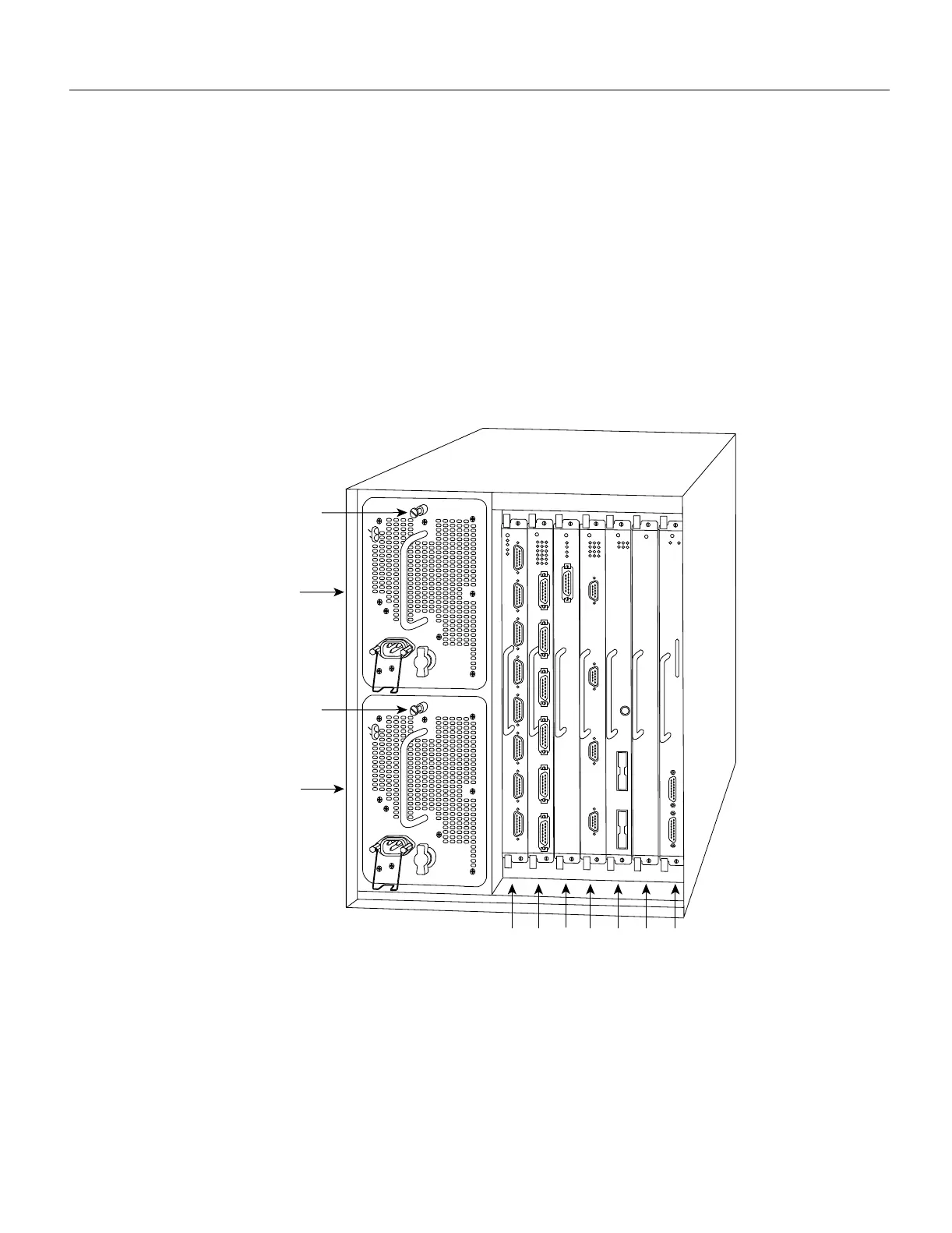
The rear of the router, shown in Figure 1-2, provides access to the seven interface slots and
removable power supplies. The lower power supply bay contains the first (standard equipment)
power supply, and the upper bay contains the second power supply (optional equipment in systems
with redundant power). The interface slots contain the RP, the SP (or the SSP) and up to five network
interface processors. When viewing the router from the rear, the RP is always located in the far right
slot (the RP slot), and the SP (or SSP) is always located in the adjacent slot (the SP slot). The
remaining five slots are numbered 0 through 4 from left to right. The five interface processor slots
support any combination of network interface types: Ethernet, Token Ring, FDDI, serial, channel
attachment, and HSSI. The RP, SP (or SSP), and interface processors are keyed with guides on the
backplane to prevent them from being fully inserted in the wrong slot.
The RP, SP, SSP, and interface processors are described in the sections that follow.
Figure 1-2 Router Rear View
H2358
Slot 0
1
2
3 4 SP
or
SSP
slot
RP
slot
Upper
power supply
Lower
power supply
I
O
DC FAIL
AC POWER
I
O
DC FAIL
AC POWER
Captive
installation screw
Captive
installation screw

 Loading...


