Maintenance 5-189
Installing and Configuring Processor Modules
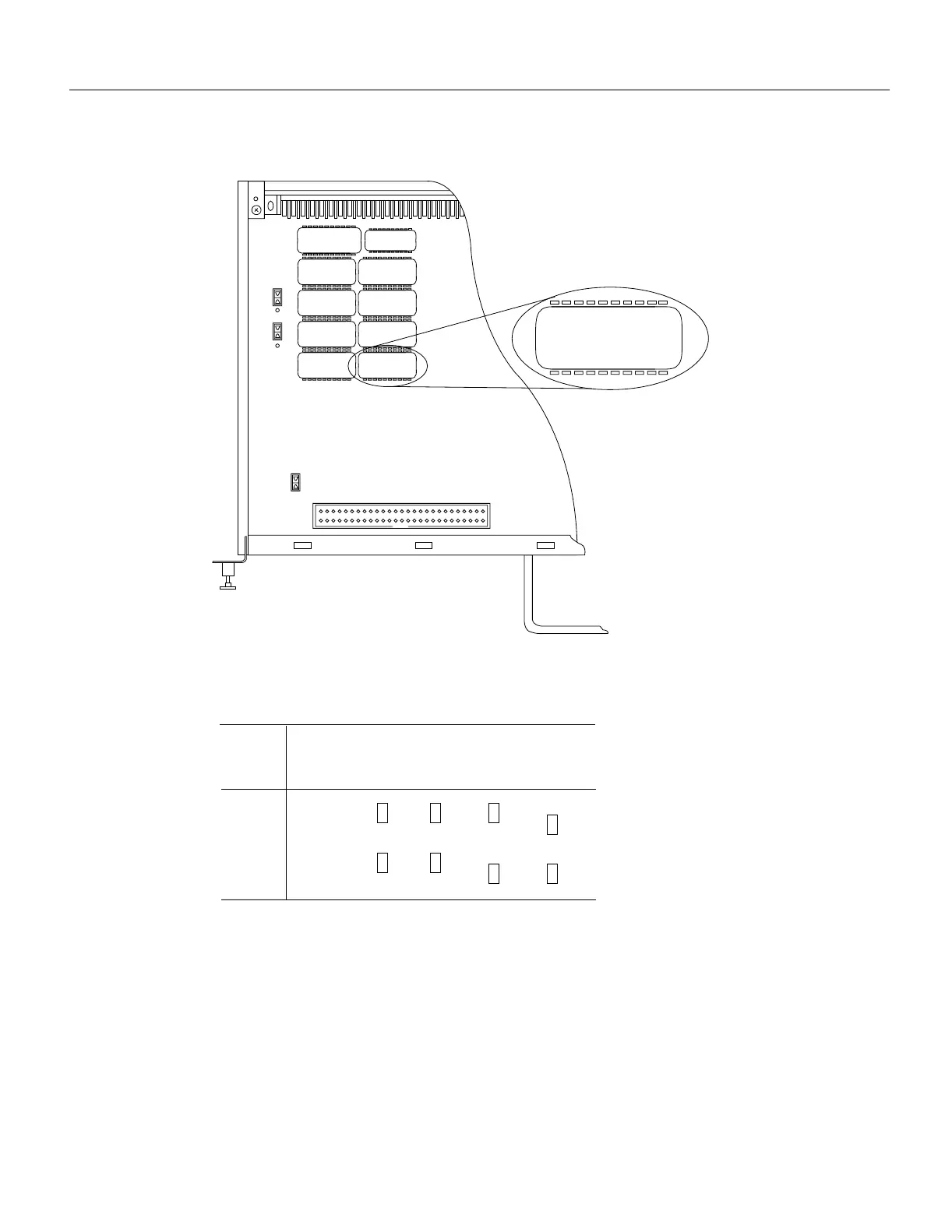
Figure 5-7 System Software ROM Sockets and Jumpers J3 and J4
Figure 5-8 Jumper Settings for Software ROM Sizes
Step 5
Use a chip extractor to remove the first EPROM from its socket. If you do not have a chip
extractor available, use the tip of a screwdriver blade to gently pry the EPROM out of its
socket.
Step 6 Install the new EPROM in the same numbered socket as old EPROM you just removed.
Observe the correct notch orientation for the new EPROM.
Step 7 Repeat Steps 5 and 6 until all new EPROMs are installed. Be careful not to bend or break
any of the pins. Use needlenose pliers to straighten a bent pin. If a pin breaks, you must
obtain a replacement.
ROM2 9.17(1)
GS7-K
©1986-93 by
cisco Systems ->eb
H1455a
ROM7
ROM5
ROM3
ROM1
ROM8
ROM6
ROM4
ROM2
J4
J3
J4
J3
EPROM
Types
Jumper
4 Mb 8 MbMemory
H1485a
.
.
.
.
.
.
.
.
.
.
.
.
.
.
.
.
.
.
27020 27040 27080
2 Mb
1
1
1
1
1
1
.
.
.
.
.
.
27010
1 Mb
1
1

 Loading...


