1-22 Cisco 7000 Hardware Installation and Maintenance
Physical Description
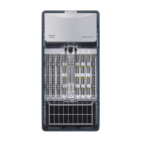
Figure 1-3 Router Chassis, Top-Down View
Figure 1-4 Router System Architecture
The backplane slots are keyed so that the RP, SP (or SSP), and interface processors can be installed
only in the slots designated for them. Keys on the backplane fit into two key guides on each processor
module. (See Figure 1-5.) While the RP and SP (or SSP) each use unique keys, all five interface
processor slots use the same key, so you can install an interface processor in any interface processor
slot, but not in the RP or SP (or SSP) slots.
H1328a
Processor
slots
Power
supply
bays
Air filter
System
blower
Air dam
LED
board
Front
of Chassis
Rear
of Chassis
Cy Bus
backplane
RP
SP or SSP
CxBus FIP
Single-port FDDI
interface processor
• 68040 CPU
• Flash EPROM
• 16-MB DRAM
• ENVM Logic
CxBus EIP
2/4/6-port Ethernet
interface processor
CxBus FSIP
4/8 port fast serial
interface processor
CxBus TRIP
2/4-port Token Ring
interface processor
Distributed processing
CxBus HIP
Single-port HSSI
interface processor
H1351a

 Loading...


