37-21
Software Configuration Guide—Release IOS XE 3.3.0SG and IOS 15.1(1)SG
OL-25340-01
Chapter 37 Configuring Bidirection Forwarding Detection
Configuration Examples for Bidirectional Forwarding Detection
Uptime: 00:04:45
Last packet: Version: 0 - Diagnostic: 0
I Hear You bit: 1 - Demand bit: 0
Poll bit: 0 - Final bit: 0
Multiplier: 3 - Length: 24
My Discr.: 6 - Your Discr.: 3
Min tx interval: 50000 - Min rx interval: 50000
Min Echo interval: 0
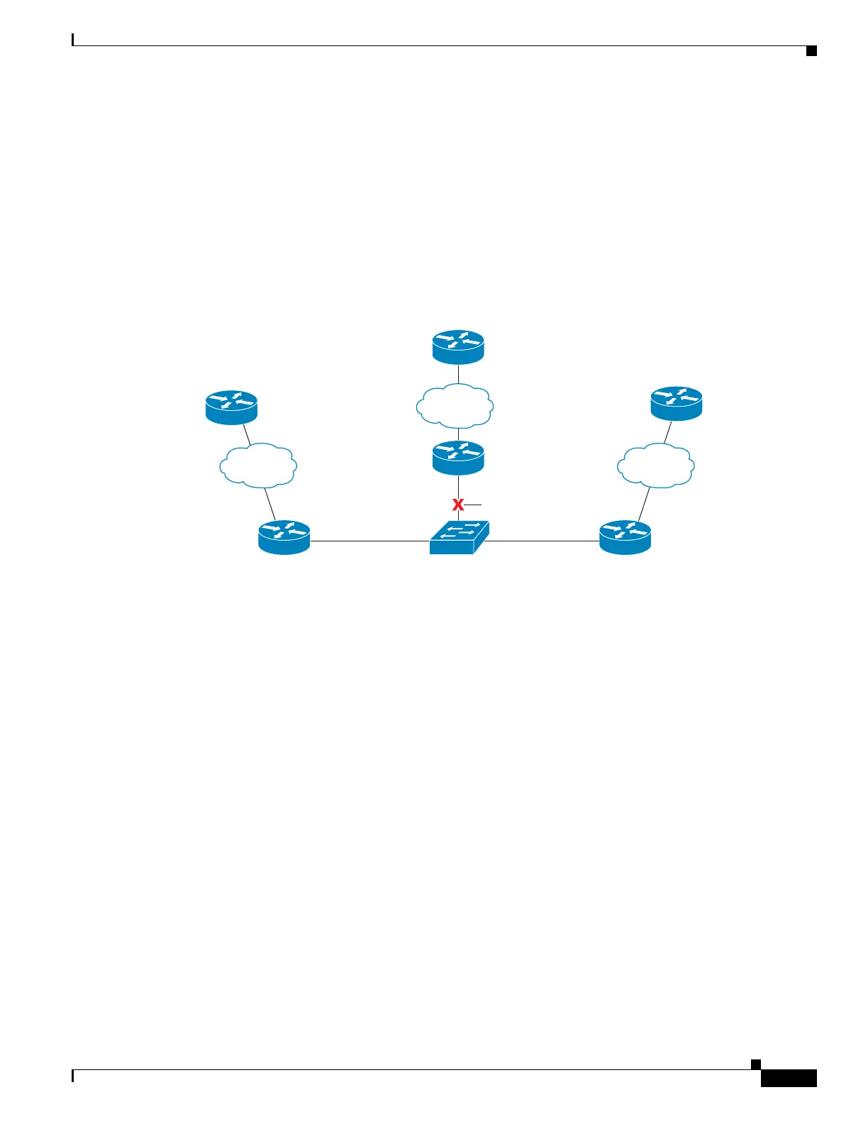
Figure 37-4 shows that Gigabit Ethernet interface 6/1 on SwitchB has failed. When Gigabit Ethernet
interface 6/1 on SwitchB is shut down, the BFD values of the corresponding BFD sessions on SwitchA
and SwitchB are reduced.
Figure 37-4 Gigabit Ethernet Interface 6/1 Failure
When Gigabit Ethernet interface 6/1 on SwitchB fails, BFD will no longer detect SwitchB as a BFD
neighbor for SwitchA or for SwitchC. In this example, Gigabit Ethernet interface 6/1 has been
administratively shut down on SwitchB.
The following output from the show bfd neighbors command on SwitchA now shows only one BFD
neighbor for SwitchA in the EIGRP network. The relevant command output is shown in bold in the
output.
SwitchA# show bfd neighbors
OurAddr NeighAddr LD/RD RH/RS Holdown(mult) State Int
172.16.1.1 172.16.1.3 5/3 1(RH) 134 (3 ) Up Gi6/1
The following output from the show bfd neighbors command on SwitchC also now shows only one BFD
neighbor for SwitchC in the EIGRP network. The relevant command output is shown in bold in the
output.
SwitchC# show bfd neighbors
OurAddr NeighAddr LD/RD RH Holdown(mult) State Int
172.16.1.3 172.16.1.1 3/5 1 114 (3 ) Up Gi6/1
Example: Configuring BFD in an OSPF Network
The following example shows how to configure BFD in an OSPF network in Cisco IOS
Release 15.1(1)SG. In the following example, the simple OSPF network consists of SwitchA and
SwitchB. Gigabit Ethernet interface 6/1 on SwitchA is connected to the same network as Gigabit
SwitchA
GigabitEthernet 6/1 GigabitEthernet 6/1
Gigabit Ethernet 6/1172.16.1.2
172.16.1.1 172.16.1.3
SwitchC
SwitchB
332677
icon indicating a failure

 Loading...


