Chapter 5 Web GUI Setup and Monitorin g
Setting up the ASI Input
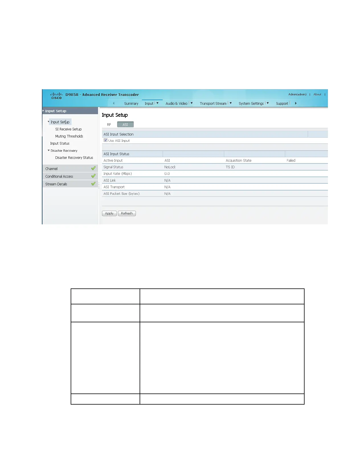
1 From the user interface of the D9858, choose Input > Input Setup. The Input
Setup page is displayed.
2 Click the ASI tab.
3 Check the Use ASI Input check box to tune to the ASI input.
Note: Setting a new input to be active will deactivate the currently active input.
4 Click Apply.
Viewing the ASI Input Status
The ASI Input Status area displays the current RF status. The following table
describes the ASI Input Status information displayed:
Indicates the currently selected input source (RF1, RF2, RF3,
RF4, or ASI).
Indicates whether the input signal is locked.
Locked - Indicates the transcoder is locked to a carrier
with no valid content.
Lock+Sig - Indicates the transcoder is locked to a
carrier with valid content.
No Lock - Indicates the transcoder is not locked to a
carrier.
Displays the bit rate of the input transport stream, in Mbps.