Connecting the Input/Output Signals
Connecting the ASI Outputs
Proceed as follows to connect to the ASI outputs:
1 Connect the output signal from the D9858 transcoder ASI OUT connectors. All
three outputs, ASI OUT 1, 2 and 3 are identical.
2 Use a Belden “Brilliance” cable with foil/braid construction. The shield must
provide 99% or better shielding effectiveness.
The equipment after the D9858 transcoder could be a Cisco D9887 HDTV
Modular Receiver or Cisco D9854 Advanced Program Receiver.
Connecting an External Alarm System
The D9858 transcoder is equipped with a connector labeled Cue Tone/Relay which
provides alarm relay outputs for remote alarm signaling. This connector provides
Cue Tone, Cue Trigger and Alarm relay functionality. See Connecting the Cue
Tone/Cue Trigger Interface (on page 28) for more information on Cue Tone and Cue
Trigger equipment connections. These contact closure outputs are user-configurable
via the Setup Menu on the front panel.
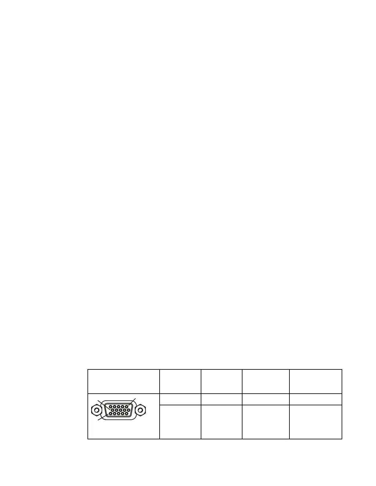
The Alarm output connector is a 15-pin sub-D female connector. The diagram below
shows the connector and the pin allocation table for the Alarm output pins.
The connector pin states depend on the selected Relay Mode. The Relay Mode is set
on the front panel. For more information, see Cueing (on page 89).
Changing the Relay Mode for Alarm Monitoring
The Alarm relay is a program relay that can be configured to provide programmed
responses for alarms, warnings, cue trigger states for ad-insertion equipment, or a
cue tone output for connection to ad-insertion equipment. As a default, the Alarm
Relay is configured for Trigger mode.
1 On the front panel menu, go the Main: Setup: Outputs, and select Cueing.
2 Use the down arrow key to scroll through the Cueing menu to Relay Mode.
3 Select Relay Mode, change the state to Alarm and press the Select key to save
the new setting. As a result, the rear panel connector pin states will change to
that shown in the table below for Alarm mode.