Note: A Normally closed state implies the state when power is applied to the relay
in a normal operating state, without a trigger or alarm condition present.
Connecting the RS-232 Data Interface
The DCE DB-9 female connector is intended for low-speed data: 7 bits, even parity, 1
stop bit, up to 38.4 kbps (default). These outputs are user-configurable via the Setup
Menu on the front panel.
The interconnect cable from the D9858 transcoder to a PC should be straight through
(for example, no handshaking), shielded and equipped with a DB-9 male connector
at one end to mate with the rear panel RS-232 Data interface, and a female DB-9
connector to connect to the PC.
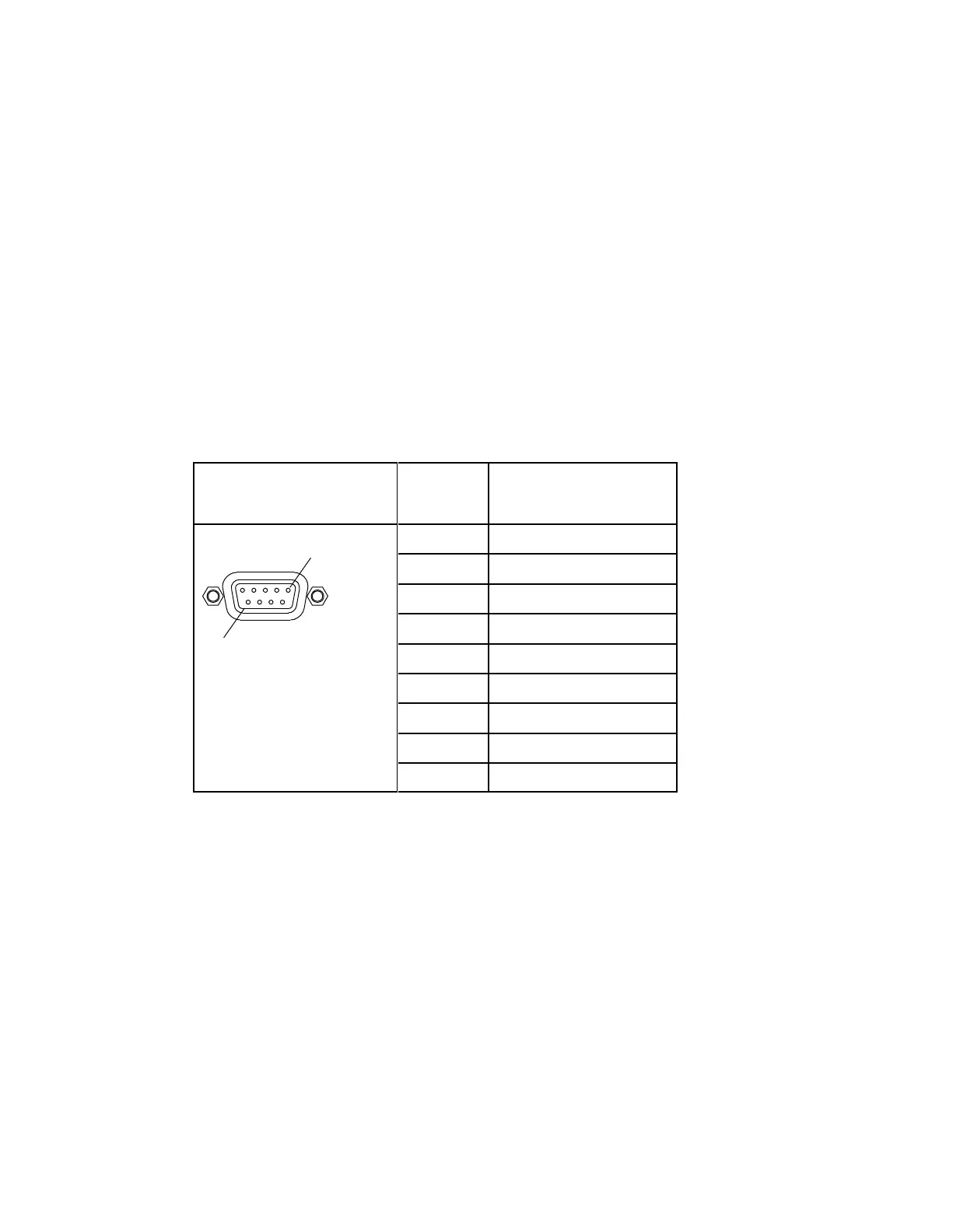
RS-232 Data Connector Pin Allocation
The table shows the RS-232 Data connector and the pin allocation:
Connecting the Cue Tone/Cue Trigger Interface
The D9858 transcoder is equipped with a connector labeled Cue Tone/Relay for
alarm relay outputs for remote alarm signaling. This connector provides Cue Tone,
Cue Trigger and Alarm relay functionality. These outputs are user-configurable via
the Setup Menu on the front panel.
The connector is a 15-pin sub-D female connector. The following diagram shows the
connector and the pin allocation table for Cue Tone, Cue Trigger and Alarm relay
connections.