Connecting the Input/Output Signals
Connecting the Input/Output Signals
Connecting the RF Inputs
Connect up to four LNB RF cables to the RF connectors labeled RF1 through RF4 on
the rear of the unit.
Use 75-ohm (braid/foil or braid/braid), low insertion loss coaxial cable.
Each input accepts an LNB signal input. RF2 to RF4 require an external LNB power
source.
Connecting the ASI Input
If desired, connect to the ASI IN port to an asynchronous serial interface for uplink
monitoring.
Connecting the Video Outputs
Connector for the Video Output
The video output connectors are of the BNC type.
Connecting the Composite Video Output
Connect a video monitor to the CVSB 1 and CVSB 2 connectors. The two outputs are
identical. Use a 75-ohm double-braided coax cable.
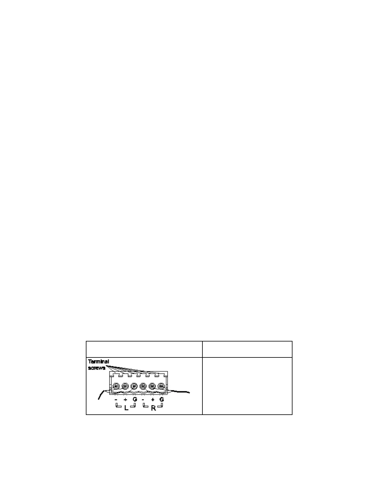
Connecting the Balanced Audio Output
1 Connect the AUDIO 1 and AUDIO 2 balanced audio outputs to monitoring
equipment. Use a multi-conductor, pluggable cable from the receiver's AUDIO 1
and AUDIO 2 (Left and Right) terminals to your equipment, as shown in the
following illustration.