672
Configuring Link State Tracking
How to Configure Link State Tracking
How to Configure Link State Tracking
Configuring Link State Tracking
Monitoring and Maintaining Link State Tracking
Configuration Examples for Configuring Link State Tracking
Displaying Link State Information: Examples
Use the show link state group command to display the link state group information. Enter this command without
keywords to display information about all link state groups. Enter the group number to display information specific to the
group. Enter the detail keyword to display detailed information about the group.
This is an example of output from the show link state group 1 command:
Switch> show link state group 1
Link State Group: 1 Status: Enabled, Down
This is an example of output from the show link state group detail command:
Switch> show link state group detail
(Up):Interface up (Dwn):Interface Down (Dis):Interface disabled
Link State Group: 1 Status: Enabled, Down
Upstream Interfaces : Fa1/7(Dwn) Fa1/8(Dwn)
Downstream Interfaces : Fa1/3(Dis) Fa1/4(Dis) Fa1/5(Dis) Fa1/6(Dis)
Link State Group: 2 Status: Enabled, Down
Upstream Interfaces : Fa1/6(Dwn) Fa1/7(Dwn) Fa1/8(Dwn)
Downstream Interfaces : Fa1/2(Dis) Fa1/3(Dis) Fa1/4(Dis) Fa1/5(Dis)
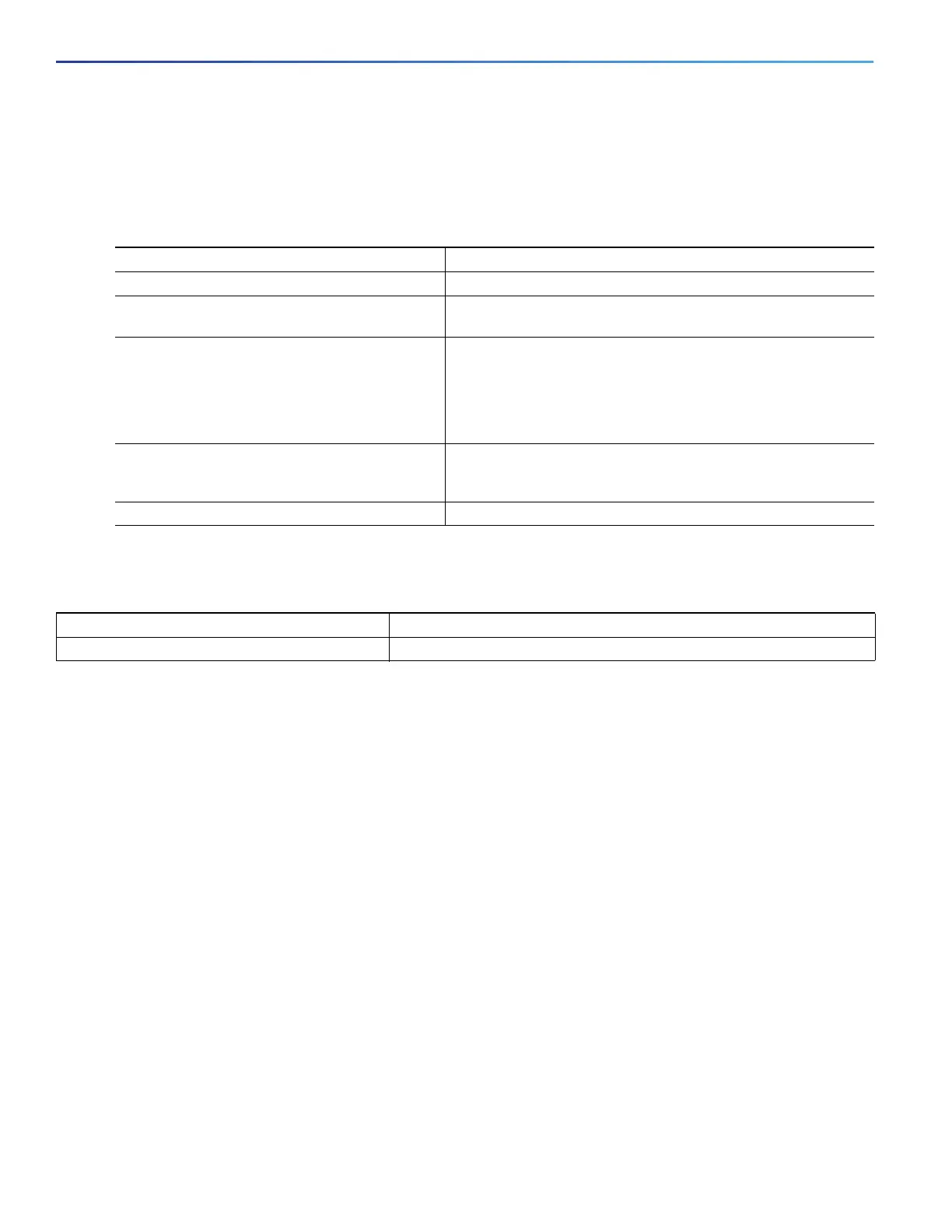
Command Purpose
1. configure terminal Enters global configuration mode.
2. link state track number Creates a link state group, and enables link state tracking. The
group number can be 1 to 2; the default is 1.
3. interface interface-id Specifies a physical interface or range of interfaces to configure,
and enters interface configuration mode.
Valid interfaces include switch ports in access or trunk mode
(IEEE 802.1q), routed ports, or multiple ports bundled into an
EtherChannel interface (static or LACP), also in trunk mode.
4. link state group [number] {upstream |
downstream}
Specifies a link state group, and configures the interface as
either an upstream or downstream interface in the group.The
group number can be 1 to 2; the default is 1.
5. end Returns to privileged EXEC mode.
Command Purpose
show link state group Displays the link state group information.

 Loading...


