320
Configuring STP
Information About Configuring STP
Forwards frames switched from another interface
Learns addresses
Receives BPDUs
Disabled State
A Layer 2 interface in the disabled state does not participate in frame forwarding or in the spanning tree. An interface in
the disabled state is nonoperational.
A disabled interface performs these functions:
Discards frames received on the interface
Discards frames switched from another interface for forwarding
Does not learn addresses
Does not receive BPDUs
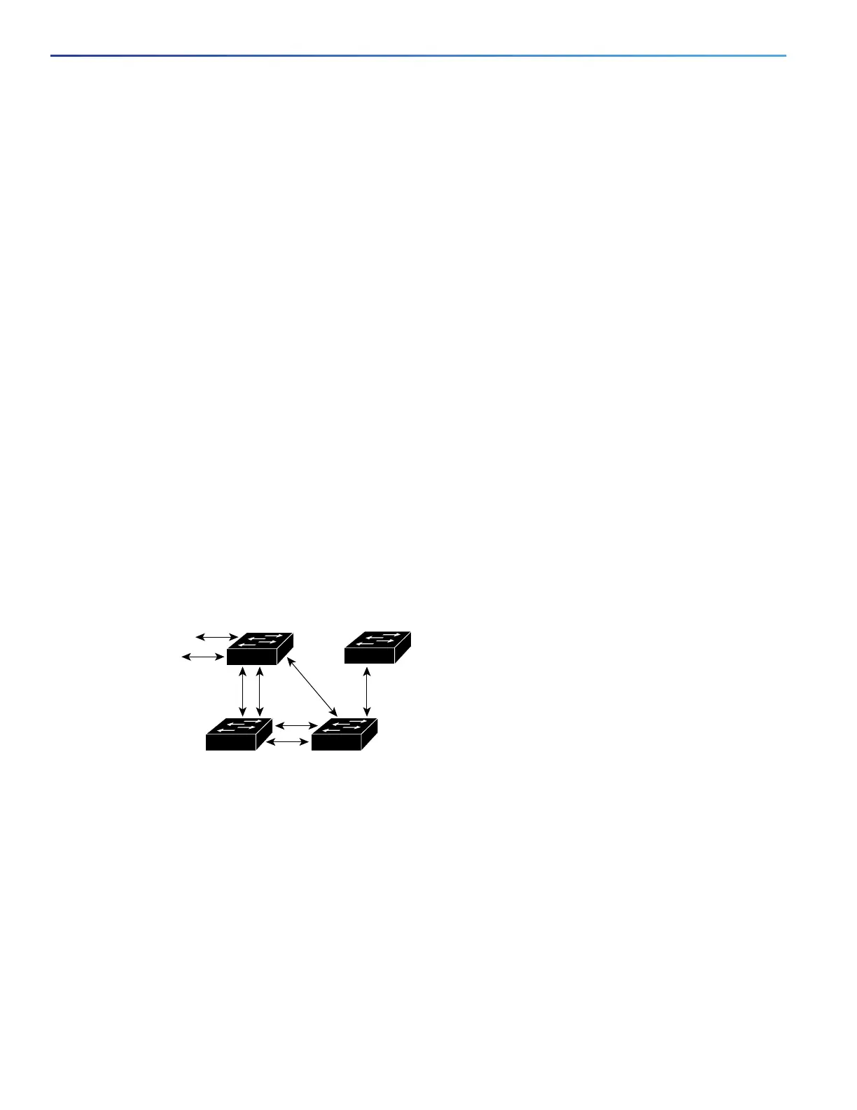
How a Switch or Port Becomes the Root Switch or Root Port
If all switches in a network are enabled with default spanning-tree settings, the switch with the lowest MAC address
becomes the root switch. In Figure 37 on page 320, Switch A is elected as the root switch because the switch priority
of all the switches is set to the default (32768) and Switch A has the lowest MAC address. However, because of traffic
patterns, number of forwarding interfaces, or link types, Switch A might not be the ideal root switch. By increasing the
priority (lowering the numerical value) of the ideal switch so that it becomes the root switch, you force a spanning-tree
recalculation to form a new topology with the ideal switch as the root.
Figure 37 Spanning-Tree Topology
When the spanning-tree topology is calculated based on default parameters, the path between source and destination
end stations in a switched network might not be ideal. For instance, connecting higher-speed links to an interface that
has a higher number than the root port can cause a root-port change. The goal is to make the fastest link the root port.
For example, assume that one port on Switch B is a Gigabit Ethernet link and that another port on Switch B (a 10/100
link) is the root port. Network traffic might be more efficient over the Gigabit Ethernet link. By changing the spanning-tree
port priority on the Gigabit Ethernet port to a higher priority (lower numerical value) than the root port, the Gigabit Ethernet
port becomes the new root port.
86475
DP
DP
RP
DP
RP
DP
RP = Root Port
DP = Designated Port
DP
RP
DA
CB

 Loading...


