• Slot 2 radio is unable to find the uplink because of a bad RF design.
• Interference and long-term fades disturb the uplink to the extent that the slot 2 radio loses its uplink
connection.
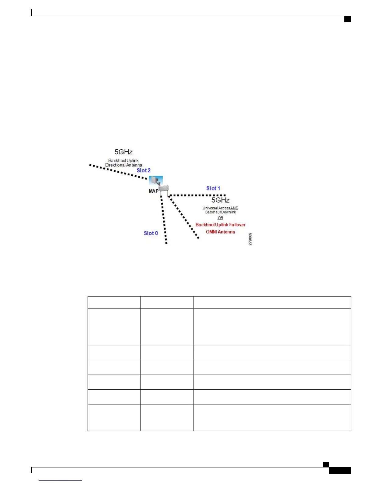
When a slot 1 radio takes over a slot 2 radio, it is called Fall Back Mode. The slot 2 radio is made inactive on
a noninterfering channel. The hardware is reduced to AP1522 (two radios). The slot 1 radio (omni antenna)
is extended to the uplink. A period of 15 minutes is set on a timer to attempt a rescan to find a parent on the
slot 2 radio again. The timer is similar to the default BGN timer.
This figure shows an example of the Fall Back Mode.
Figure 3: Fall Back Mode
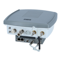
The antenna ports are labeled on the AP1524SB and are connected internally to the radios in each slot.
The AP1524SB has six ports with three radio slots (0, 1, 2) as described in Table 2: AP1524SB Antenna
Ports, on page 13.
Table 2: AP1524SB Antenna Ports
DescriptionRadio SlotAntenna Port
5 GHz–Used for backhaul and universal access. Universal access
is configured only on slot 1.
Omni antenna is
required.
Note
11
2 GHz–Used for client access.02
2 GHz–Used for client access.03
2 GHz–Used for client access.04
Not connected.—5
5 GHz–Used for backhaul.
Directional antenna is
required.
Note
26
Cisco Mesh Access Points, Design and Deployment Guide, Release 7.3
OL-27593-01 13
Mesh Network Components
Cisco Outdoor Mesh Access Points