InteliCompact
NT
, SW version 2.1
InteliCompact-NT-2.1-Reference Guide.pdf, ©ComAp – May 2015
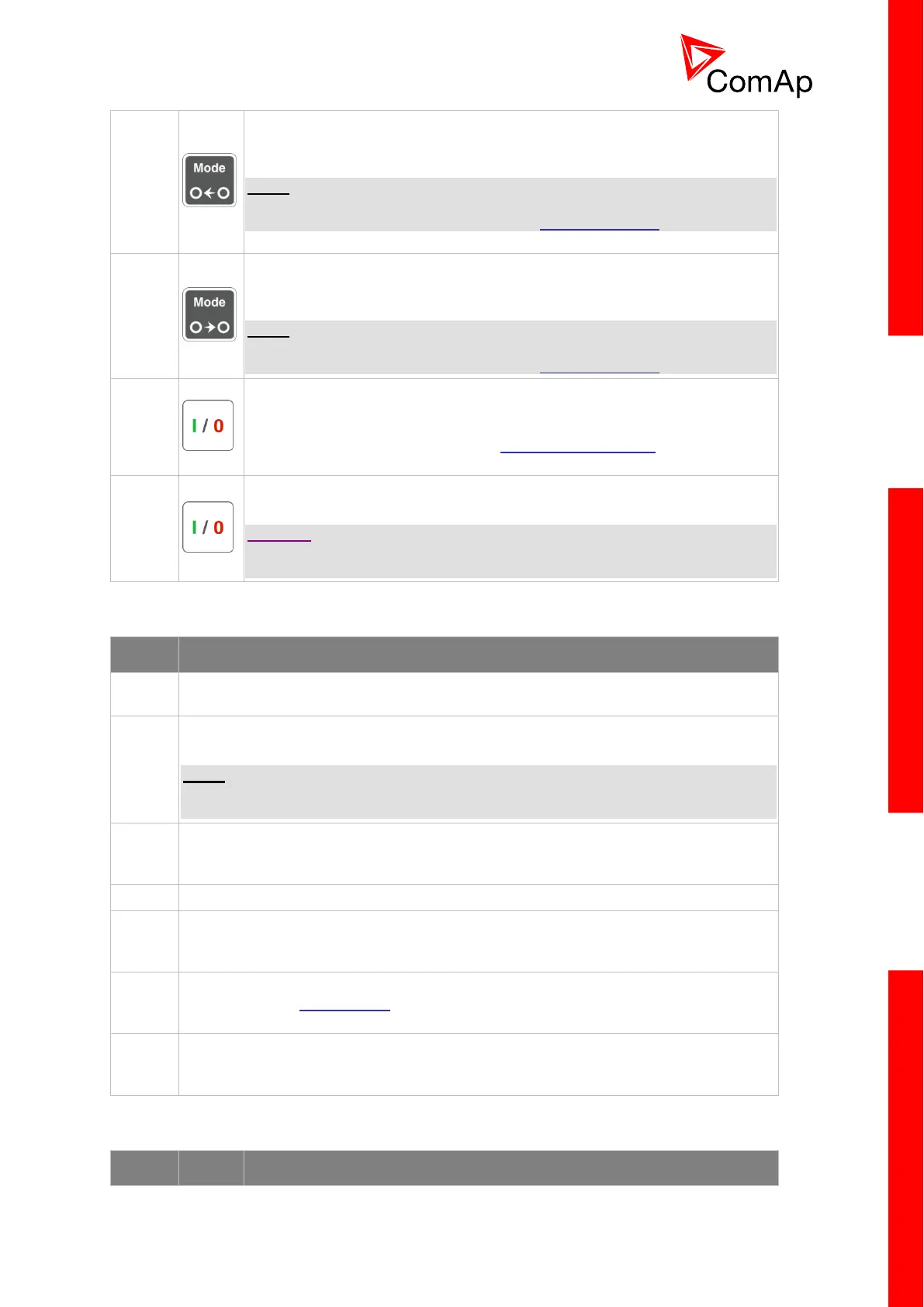
MODE LEFT button. Use this button to change the mode. The button works
only if the main screen with the indicator of the currently selected mode is
displayed.
NOTE:
This button will not work if the controller mode is forced by one of the binary
inputs listed in the Reference Guide in the Operating modes chapter.
MODE RIGHT button. Use this button to change the mode. The button
works only if the main screen with the indicator of the currently selected
mode is displayed.
NOTE:
This button will not work if the controller mode is forced by one of the binary
inputs listed in the Reference Guide in the Operating modes chapter.
GCB button. Works in MAN and TEST modes only. Press this button to
open or close the GCB or start synchronizing manually. Note that certain
conditions must be fulfilled otherwise GCB closing (starting of
synchronization) is blocked. See the Connecting to the load chapter in the
Reference Guide for details.
MCB button. Works in MAN and TEST modes only. Press this button to
open or close the MCB or start the reverse synchronizing manually.
CAUTION!
You can disconnect the load from the mains supply with this button! Be sure
you are well aware of what you are about to do!
GEN-SET OPERATION INDICATORS
General alarm. This red indicator lights up if at least one alarm is present in the alarm
list. It blinks if a new alarm has appeared and is still not acknowledged.
Gen-set voltage OK. This green indicator lights up if the generator voltage and
frequency is within the limits.
NOTE:
The limits for the generator voltage and frequency are given by setpoints in the Gener
Protect group.
GCB position. This green indicator blinks if the forward synchronizing is currently in
progress; otherwise it shows the current status of the generator circuit breaker
according to the feedback input.
Bus under voltage. This green indicator shows if the bus is under voltage or not.
MCB position. This green indicator blinks if the reverse synchronizing is currently in
progress; otherwise it shows the current status of the mains circuit breaker according
to the feedback input.
Mains voltage OK. This green indicator lights up if the mains are evaluated as
healthy. See the AMF function chapter in the Reference Guide for details about mains
evaluation.
Mains failure. This red indicator starts blinking when mains failure is detected. After
the gen-set has started and is about to take the load, it lights up permanently until the
mains failure disappears.
DISPLAY AND DISPLAY CONTROL BUTTONS