NOTE:
The governor and AVR must be adjusted properly to achieve these limits as the controller does not
perform any regulation and the regulation outputs have constant values given by the AVRi Bias and
Speed Gov Bias setpoints.
There are two ways to connect the gen-set to the load (bus bar). This depends on the state of MCB
feedback and on the measured mains/bus voltage.
6.6.1 Connecting to dead bus
SPtM: if the MCB is open, the bus bar is considered as voltage-free and the GCB is closed without
synchronizing.
MINT: the measured bus voltage is also taken in account and it must be below 2% of the nominal bus
voltage together with the open MCB to close the GCB without synchronizing.
NOTE:
If the group of gen-sets is activated and multiple gen-sets have to start simultaneously and connect to
the empty bus bar, there is an internal logic to prevent closing of more GCBs to the bus bar at the
same moment without synchronizing. One of the gen-sets will close the GCB, the others will wait and
then they will synchronize to the first one.
NOTE:
There also is a protection of “Bus power loss sensing”. The “Bus Measure Error” is detected in MINT
application when the voltage on the controller’s bus terminals is out of limits 20 seconds after:
a) GCB (own) was closed in MAN or AUT mode
b) MCB (feedback) was closed in AUT mode
c) Any other GCB in power management group (on CAN bus) was closed.
The alarm is activated after 20s. However, the GCB (own) closing is blocked immediately for safety
reasons.
This protection can avoid e.g. potential direct closing of GCB while the controller’s bus conductors are
unintentionally unplugged from the terminals.
6.6.2 Synchronizing
SPtM: If the MCB is closed, the bus bar is considered to have identical voltage as measured on the
mains. If the mains voltage/frequency is within limits, the gen-set is first synchronized with the mains
and then the GCB is closed.
MINT: If the measured bus voltage is within limits, the gen-set is first synchronized with the bus and
then the GCB is closed.
The synchronizing consists of voltage matching and frequency/angle matching. The maximum
duration of synchronizing is given by the setpoint Sync Timeout. If the synchronizing is not successful
within this period of time, the Sync Timeout alarm will be issued.
NOTE:
The synchronization will be interrupted automatically if any of the necessary conditions disappear
during the synchronization process.
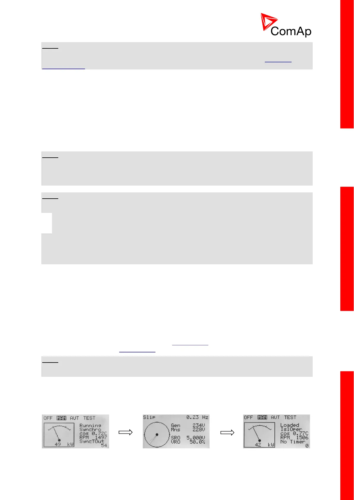
When the controller starts to synchronize (the event will change to “Synchro”) and the Main Measuring
screen is displayed, it will be automatically change to the Synchroscope screen for the entire duration
of synchronization. After synchronization the Synchroscope screen is automatically changed back to
the Main Measuring screen.