TaLk
8-t.
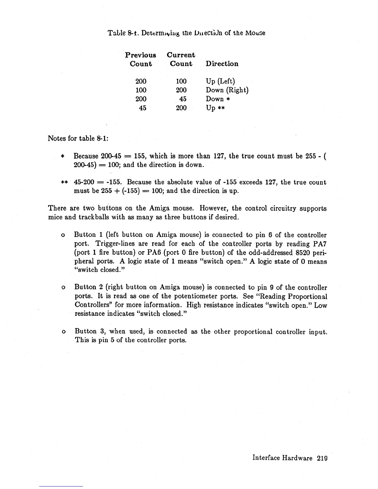
Dcttfml~il1s
ttle vueCt'iJn of the Mouse
Previous
Current
Count
Count
Direction
200
100
Up (Left)
100
200
Down (Righ t)
200
45
Down *
45
200
Up
**
Notes for table 8-1:
* Because 200-45 = 155, which is more than 127, the true count must be
255
- (
200-45)
=
100;
and the direction is down.
**
45-200 = -155. Because the absolute value of -155 exceeds 127, the true count
must be 255
+ (-155) =
100;
and the direction is up.
There are two buttons on the Amiga mouse. However, the control circuitry supports
mice and trackballs with as many as three buttons if desired.
o Button 1 (left button on Amiga mouse) is connected to pin 6 of the controller
port. Trigger-lines are read for each of the controller ports by reading PA7
(port 1 fire button) or PA6 (port 0
fire
button) of the odd-addressed 8520 peri-
pheral ports. A logic
state
of 1 means "switch open." A logic
state
of 0 means
"switch closed."
o Button 2 (right button on Amiga mouse) is connected
to
pin 9 of the controller
ports.
It
is read as one of the potentiometer ports. See "Reading Proportional
Controllers" for more information. High resistance indicates "switch open."
Low
resistance indicates "switch closed."
o Button
3,
when used,
is
connected as the other proportional controller input.
This
is
pin 5 of the controller ports.
Interface Hardware
219