>-
~
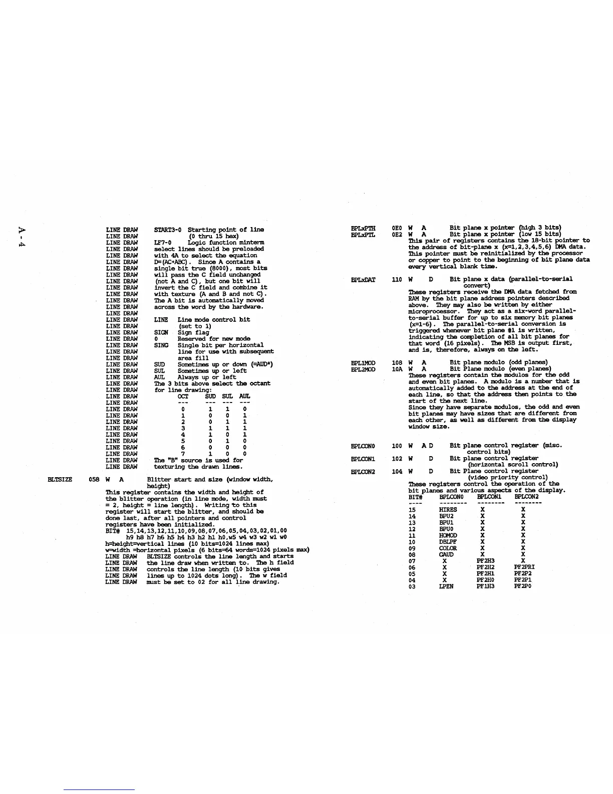
BLTSlZE
LINE
DRAW
START3-0
Starting
point
of
line
LINE
DRAW
(0
thru
15
hex)
LINE
DRAW
LF7-0
Logic
function
mintenn
LINE
DRAW
select
lines
should
be
preloaded
LINE
DRAW
with
4A
to
select
the
equation
LINE
DRAW
D=
(AC+ABC).
Since
A
contains
a
LINE
DRAW
single
bit
true
(8000),
most
bits
LINE
DRAW
will
pass
the
C
field
unchanged
LINE
DRAW
(not
A
and
C),
but
one
bit
will
LINE
DRAW
invert
the
C
field
and
colnbine
it
LINE
DRAW
with
texture
(A
and
B
and
not
C)
•
LINE
DRAW
The
A
bit
is
automatically
moved
LINE
DRAW
LINE
DRAW
across
the
word
by
the
hardware.
LINE
DRAW
LINE
Line
mode
control
bit
LINE
DRAW
(set
to
1)
LINE
DRAW
SIGN
Sign
flag
LINE
DRAW
0
Reserved
for
new
mode
LINE
DRAW
SING
Single
bit
per
horizontal
LINE
DRAW
line
for
use
with
subsequent
LINE
DRAW
area
fill
LINE
DRAW
SUD
Sometimes up
or
down
(=AUD*)
LINE
DRAW
SUL
Sometimes up
or
left
LINE
DRAW
AUt
Always up
or
left
LINE
DRAW
The
3
bits
above
select
the
octant
LINE
DRAW
for
line
drawing:
LINE
DRAW
OCT
SUD
SUL
AUL
LINE
DRAW
LINE
DRAW
0
1
1
0
LINE
DRAW
1 0
0 1
LINE
DRAW
2 0
1
1
LINE
DRAW
3
1 1 1
LINE
DRAW
4
1
0
1
LINE
DRAW
5
0
1
0
LINE
DRAW
6
0 0 0
LINE
DRAW
7
1 0 0
LINE
DRAW
The
"B"
source
is
used
for
LINE
DRAW
texturing
the
drawn
lines.
058 W A
Blitter
start
and
size
(window
width,
height)
This
register
contains
the
width
and
height
of
the
blitter
operation
(in
line
mode,
width
IDJ.St
=
2,
height
=
line
length).
Writing
'to
this
register
will
start
the
blitter,
and
should
be
done
last,
after
all
pointers
and
control
registers
have
been
initialized.
BIT#
15,14,13,12,11,10,09,08,07,06,05,04,03,02,01,00
h9 h8
h7
h6
h5
h4 h3
h2 h1
hO,w5
w4
w3
w2
wl
wO
h=height=vertical
lines
(10
bits=1024
lines
max)
w=width
=horizontal
pixels
(6
bits=64
words=1024
pixels
max)
LINE
DRAW
BLTSlZE
controls
the
line
length
and
starts
LINE
DRAW
the
line
draw
when
written
to.
The
h
field
LINE
DRAW
controls
the
line
length
(10
bits
gives
LINE
DRAW
lines
up
to
1024
dots
long).
The
w
field
LINE
DRAW
IDJ.St
be
set
to
02
for
all
line
drawing.
BPLxPm
BPLxPTL
BPLlMOD
BPL2MJD
BPLCONO
BPLCONl
BPLCON2
OEO
W A
Bit
plane
x
pointer
(high
3
bits)
OE2
W A
Bit
plane
x
pointer
(low
15
bits)
This
pair
of
registers
contains
the
18-bit
pointer
to
the
address
of
bit-plane
x
(x=1,2,3,4,5,6)
DMA
data.
This
pointer
IDJ.St
be
reinitialized
by
the
processor
or
copper
to
point
to
the
beginning
of
bit
plane
data
every
vertical
blank
time.
110 W D
Bit
plane
x
data
CParallel-to-serial
convert)
These
registers
receive
the
DMA
data
fetched
from
RAM
by
the
bit
plane
address
pointers
described
above.
They
may
also
be
written
by
either
microprocessor.
They
act
as
a
six-word
parallel-
to-serial
buffer
for
up
to
six
memory
bit
planes
(x=1-6).
The
parallel-to-serial
conversion
is
triggered
whenever
bit
plane
#1
is
written,
indicating
the
completion
of
all
bit
planes
for
that
word (16
pixels).
The
MBB
is
output
first,
and
is,
therefore,
always
on
the
left.
108 W A
Bit
plane
modulo (odd
planes)
lOA
W A
Bit
Plane
modulo (even
planes)
100
102
104
These
registers
contain
the
modulos
for
the
odd
and
even
bit
planes.
A modulo
is
a number
that
is
automatically
added
to
the
address
at
the
end
of
each
line,
so
that
the
address
then
points
to
the
start
of
the
next
line.
Since
they
have
separate
modulos,
the
odd
and
even
bit
planes
may
have
sizes
that
are
different
from
each
other,
as
well
as
different
from
the
display
window
size.
W
AD
Bit
plane
control
register
control
bits)
(misc.
W D
Bit
plane
control
register
W D
(iborizontal
scroll
control)
Bit
Plane
control
register
(video
priority
control)
These
registers
control
the
operation
of
the
bit
planes
and
various
aspects
of
the
display.
BIT#
BPLCONO
BPLCONl
BPLCON2
--------
--------
--------
15
HIRES
X
X
14
BPU2
X
X
13
BPUl
X
X
12
BPUO
X
X
11
HOMOD
X
X
10
DBLPF
X
X
09
COLOR
X
X
08
GAUD
X
X
07 X PF2H3
X
06
X
PF2H2
PF2PRI
05
X PF2H1 PF2P2
04
X
PF2HO
PF2Pl
03
LPEN
PF1H3
PF2PO