CLXCON
>
en
02
LACE
PFlH2
PFlP2
01
ERSY
PFlHl
PFlPl
00
X
PFlHO
PFlPO
IDRES=Hlgh-resolution
(640) mode
BPU
=Bit·plane
use
code
000-110
(NONE
through
6
inclusive)
lDIOD=Hold-and-modify mode
DBLPF=Double
playfield
(pF1=odd PF2=even
bit
planes)
COLOR=CoIIposite
video
COLOR
enable
GlWD=Genlock
audio
enable
(muxed
on
BKGND
pin
during
vertical
blanking
LPEN
=Light
pen
enable
(reset
on
power up)
LACE
=Interlace
enable
(reset
on
power up)
ERSY
=External
resync
(HSYNC,
VSYNC
pads
become
Inputs)
(reset
on
power up)
PF2PRI=Playfield
2
(even
planes)
has
priority
over
(appears
in
front
of)
playfield
1
(odd
planes)
.
PF2P=Playfield
2
priority
code
(with
respect
to
sprites)
PF1P=Playfield
1
priority
code
(with
respect:
to
sprites)
PF2H=Playfield
2
horizontal
scroll
code
PFlH=Playfield
1
horizontal
scroll
code
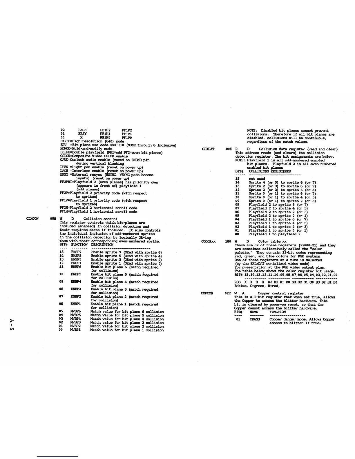
098 W D
Collision
control
This
register
controls
which
bit-planes
are
included
(enabled)
in
collision
detection
and
their
required
state
if
included.
It
also
controls
the
individual
inclusion
of
odd-numbered
sprites
in
the
collision
detection
by
logically
OR-ing
them
with
their
corresponding
even-numbered
sprite.
BIT#
FUNCTION
DESCRIPTION
--------
------------------------------
15
ENSP7
Enable
sprite
7
(ORed
with
sprite
6)
14
ENSP5
Enable
sprite
5
(ORed
with
sprite
4)
13
ENSP3
Enable
sprite
3
(ORed
with
sprite
2)
12
ENSP1
Enable
sprite
1
(ORed
with
sprite
0)
11
ENBP6
Enable
bit
plane
6 (match
required
for
colltsion)
10
ENBP5
Enable
bit
plane
5
(match
fequired
09
for
collision)
ENBP4
Enable
bit
plane
4
(match
required
for
collision)
08
ENBP3
Enable
bit
plane
3
(match
required
for
collision)
07
ENBP2
Enable
bit
plane
2
(match
required
for
collision)
06
ENBPI
Enable
bit
plane
1
(match
required
for
collision)
05
MVBP6
Match
value
for
bit
plane
6
collision
04
MVBP5
Match
value
for
bit
plane
5
collision
03
MVBP4
Match
value
for
bit
plane
4
collision
02
MVBP3
Match
value
for
bit
plane
3
collision
01
MVBP2
Match
value
for
bit
plane
2
collision
00
MVBP1
Match
value
for
bit
plane
1
collision
COLORxx
COPCON
NOTE:
Disabled
bit
planes
cannot
prevent
collisions.
Therefore
if
all
bit
planes
are
disabled,
collisiOns
will
be
continuous,
regardless
of
the
match
values.
OOE
R D
Collision
data
register
(read
and
clear)
This
address
reads
(and
clears)
the
collision
detection
register.
The
bit
assignments
are
below.
NOTE:
Playfield
1
is
all
odd-numbered
enabled
bit
planes.
Playfield
2
is
all
even-numbered
enabled
bit
planes
BIT#
COLLISIONS
REGISTERED
15
not
used
14
Sprite
4
(or
5)
to
sprite
6
(or
7)
13
Sprite
2
(or
3)
to
sprite
6
(or
7)
12
Sprite
2
(or
3)
to
sprite
4
(or
5)
11
Sprite
0
(or
1)
to
sprite
6
(or
7)
10
Sprite
0
(or
1)
to
sprite
4
(or
5)
09
Sprite
0
(or
1)
to
sprite
2
(or
3)
08
Playfield
2
to
sprite
6
(or
7)
07
Playfield
2
to
sprite
4
(or
5)
06
Playfield
2
to
sprite
2
(or
3)
05
Playfield
2
to
sprite
0
(or
1)
04
Playfield
1
to
sprite
6
(or
7)
03
Playfield
1
to
sprite
4
(or
5)
02
Playfield
1
to
sprite
2
(or
3)
01
Playfield
1
to
sprite
0
(or
1)
00
Playfield
1
to
playfield
2
180
W D
Color
table
xx
There
are
32
of
these
registers
(xx=00-31)
and
they
are
sometimes
collectively
called
the
"color
palette."
They
contain
12-bit
codes
representing
red,
green,
and
blue
colors
for
RGB
systEIIIS.
One
of
these
registers
at
a
time
is
selected
(by
the
BPLxDAT
serialized
video
code)
for
presentation
at
the
RGB
video
output
pins.
The
table
below
shows
the
color
register
bit
usage.
BIT#
15,14,13,12,11,10,09,08,07,06,05,04,03,02,01,00
RGBXXXX~~~~~~m~~~m~
B=blue,
G=green,
R=red,
OlE
W A
Copper
control
register
This
is
a
I-bit
register
that
when
set
true,
allows
the
Copper
to
access
the
blitter
hardware.
This
bit
is
cleared
by
power-on
reset,
so
that
the
Copper
cannot
access
the
blitter
hardware.
BIT#
NAME
FUNCTION
01
Copper
danger
mode.
Allows
Copper
access
to
blitter
if
true.