>
.....
0
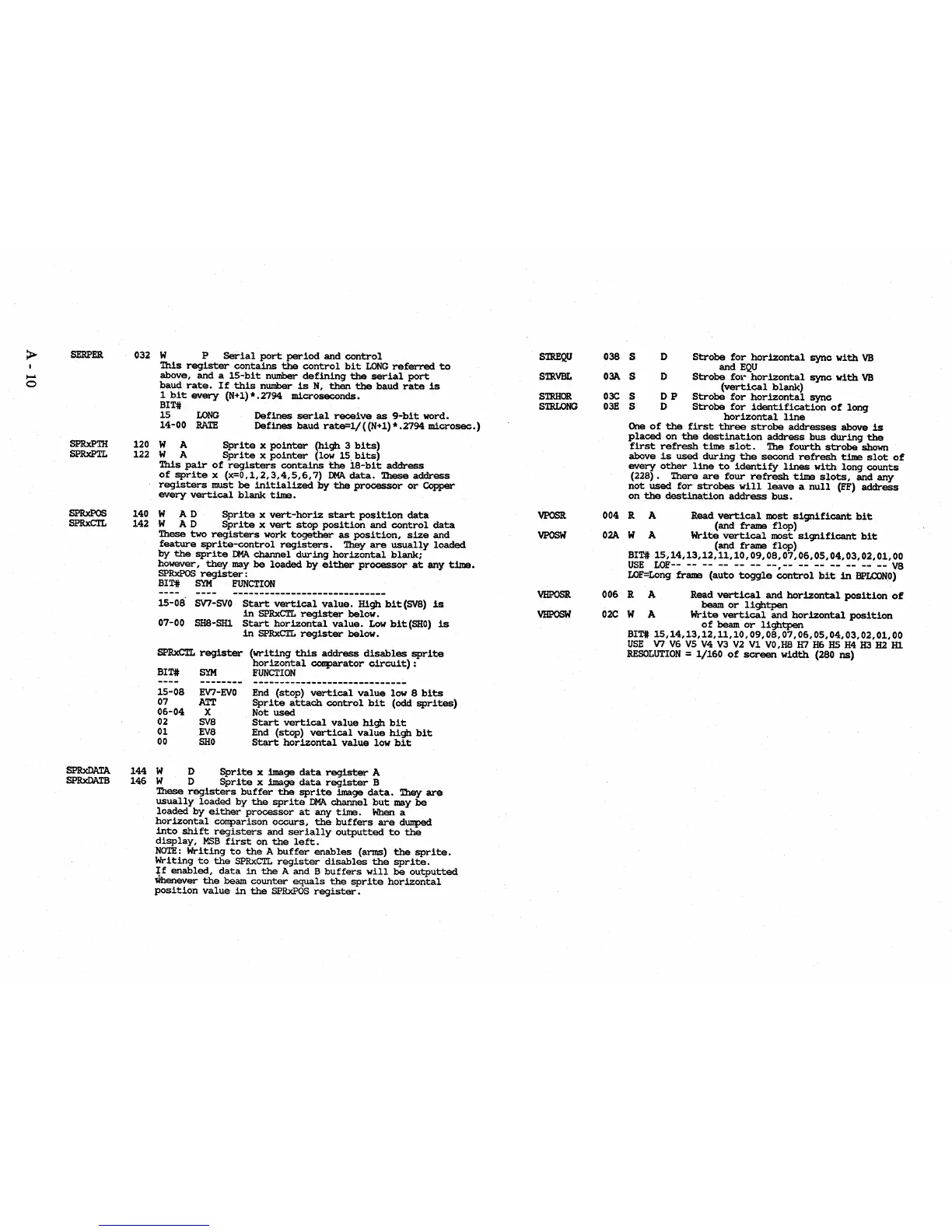
SERPER
SPRxPTH
SPRxPTL
SPRxPOS
SPRxCTL
SPRxDATA
SPRxDATB
032
W
P
Serial
port
period
and
control
This
register
contains
the
control
bit
LONG
referred
to
above,
and
a
15-bit
number
defining
the
serial
port
baud
rate.
If
this
number
is
N,
then
the
baud
rate
is
1
bit
every
(N+l)*.2794
BIT#
microseconds.
15
LONG
Defines
serial
receive
as
9-bit
word.
14-00
RATE
Defines
baud
rate=l/
«N+
1)
* • 2794
microsec.)
120 W
A
Sprite
x
pointer
(high
3
bits)
122
W
A
Sprite
x
pointer
(low
15,bits)
This
pair
of
registers
contains
the
lS-bit
address
of
sprite
x
(X=O,1,2,3,4,5,6,7)
DMA
data.
These
address
registers
must
be
initialized
by
the
processor
or
Copper
every
vertical
blank
time.
140
WAD
Sprite
x
vert-horiz
start
position
data
142
WAD
Sprite
x
vert
stop
position
and
control
data
These
two
registers
work
together
as
poSition,
size
and
feature
sprite-control
registers.
They
are
usually
loaded
by
the
sprite
DMA
channel
during
horizontal
blank;
however,
they
may
be
loaded
by
either
processor
at
any
time.
SPRxPOS
register:
BIT#
SYM
FUNCTION
15-08
SV7-SVO
Start
vertical
value.
High
bit(SV8)
is
in
SPRxCTL
register
below.
07-00
SHS-SHl
Start
horizontal
value.
Low
bit(SHO)
is
in
SPRxCTL
register
below.
SPRxCTL
register
(writing
this
address
disables
sprite
horizontal
comparator
circuit):
BIT#
SYM
FUNCTION
15-08
07
06-04
02
01
00
EV7-£IIO
ATT
X
SVS
EVS
SHO
End
(stop)
vertical
value
low
8
bits
Sprite
attach
control
bit
(odd
sprites)
Not
used
Start
vertical
value
high
bit
End
(stop)
vertical
value
high
bit
Start
horizontal
value
low
bit
144
W D
Sprite
x
image
data
register
A
146
W D
Sprite
x image
data
register
B
These
registers
buffer
the
sprite
image
data.
They
are
usually
loaded
by
the
sprite
DMA.
channel
but
may
be
loaded
by
either
processor
at
any
time.
When
a
horizontal
comparison
occurs,
the
buffers
are
dumped
into
shift
registers
and
serially
outputted
to
the
display,
MSB
first
on
the
left.
NOTE:
Writing
to
the
A
buffer
enables
(arms)
the
sprite.
Writing
to
the
SPRxCTL
register
disables
the
sprite.
If
enabled,
data
in
the
A
and
B
buffers
will
be
outputted
tfuenever
the
beam
counter
equals
the
sprite
horizontal
position
value
in
the
SPRxPOS
register.
STREQU
STRVBL
STRHOR
STRLONG
VPOSR
VPOSW
VHI?OSR
VHPOSW
038
OM
03C
03E
S D
Strobe
for
horizontal
sync
with
VB
and
EQU
S D
Strobe
fOl-
horizontal
sync
with
VB
(vertical
blank)
S D P
Strobe
for
horizontal
sync
S D
Strobe
for
identification
of
long
horizontal
line
One
of
the
first
three
strobe
addresses
above
is
placed
on
the
destination
address
bus
during
the
first
refresh
time
slot.
The
fourth
strobe
shown
above
is
used
during
the
second
refresh
time
slot
of
every
other
line
to
identify
lines
with
long
counts
(22S).
There
are
four
refresh
time
slots,
and
any
not
used
for
strobes
will
leave
a
null
(FF)
address
on
the
destination
address
bus.
004 R A Read
vertical
most
significant
bit
(and
frame
flop)
02A
W A
Write
vertical
most
significant
bit
(and
frame
flop)
BIT#
15,14,13,12,11,10,09,OS,07,06,05,04,03,02,01,00
USE
LOF--
--
--
--
-- --
--,--
-- --
--
-- --
--
V8
LOF=Long
frame
(auto
toggle
control
bit
in
BPLCONO)
006 R A Read
vertical
and
horizontal
position
of
beam
or
lightpen
02C
W A
Write
vertical
and
horizontal
position
of
beam
or
lightpen
BIT#
15,14,13,12,11,10,09,OS,07,06,05,04,03,02,01,OO
USE
V7
V6
V5
V4
V3
V2
V1
VO,HS
H7
H6
H5
H4
H3
H2
H1
RESOLUTION
=
1/160
of
screen
width
(280
ns)