JOYTEST
POTODAT
POTlDAT
POTOO
POTOOR
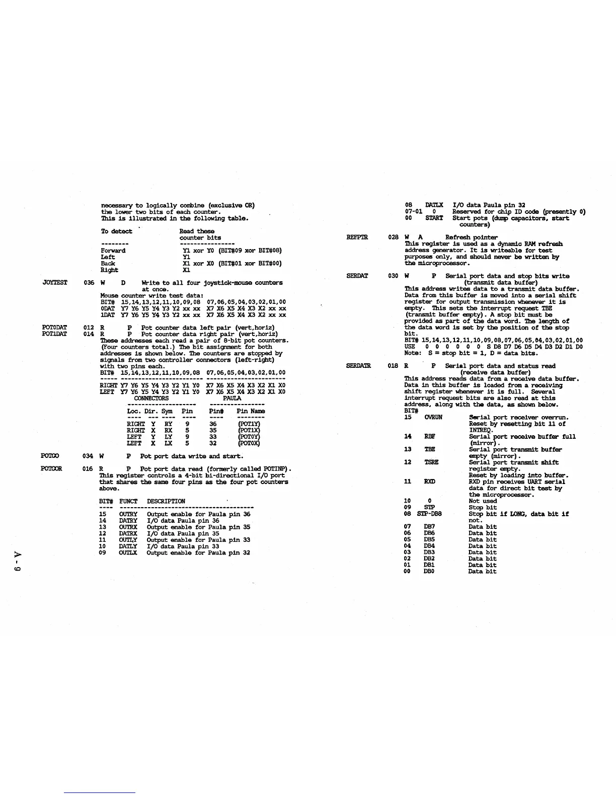
necessary
to
logically
combine
(exclusive
OR)
the
lower
two
bits
of
each
counter.
This
is
illustrated
in
the
following
table.
To
detect
Forward
Left
Back
Right
Read
these
counter
bits
Yl
xor
YO
(BIT#09
xor
BIT#08)
Y1
Xl
xor
XO
(BIT#Ol
xor
BIT#OO)
Xl
036 W D
Write
to
all
four
joystick-mouse
counters
at
once.
Mouse
counter
write
test
data:
BIT#
15,14,13,12,11,10,09,08
07,06,05,04,03,02,01,00
ODAT
Y7
Y6
YS
Y4
Y3 Y2
xx
xx
X7
X6
X5
X4
X3
X2
xx xx
lDAT
Y7
Y6
YS
Y4
Y3
Y2
xx xx
X7
X6
X5
X4
X3
X2
xx xx
012 R P
Pot
counter
data
left
pair
(vert,horiz)
014 R P
Pot
counter
data
right
pair
(vert,horiz)
These
addresses
each
read
a
pair
of
8-bit
pot
counters.
(Four
counters
total.)
The
bit
assignment
for
both
addresses
is
shown
below.
The
counters
are
stopped
by
signals
from two
controller
connectors
(left-right)
with
two
pins
each.
BIT#
15,14,13,12,11,10,09,08
07,06,05,04,03,02,01,00
RIGHT
Y7
Y6
YS
Y4
Y3 Y2
Yl
YO
X7
X6
X5
X4
X3
X2
Xl
XO
LEFT
Y7
Y6
YS
Y4
Y3 Y2
Y1
YO
X7
X6
X5
X4
X3
X2
Xl
XO
CONNECTORS
PAUIA
Loe.
Dir.
Sym
Pin
Pin#
Pin
Name
----
---
----
--------
RIGHT
Y
RY
9
36
(POT1Y)
RIGHT
X
RX
5
35
(POTlX)
LEFT
Y
LY
9
33
(POTOY)
LEFT
X
LX
5
32
(POTOX)
034 W P
Pot
port
data
write
and
start.
016 R P
Pot
port
data
read
(formerly
called
POTINP).
This
register
controls
a
4-bit
bi-directional
I/O
port
that
shares
the
same
four
pins
as
the
four
pot
counters
above.
BIT#
FUNCT
DESCRIPTION
15
14
13
12
11
10
09
OUTRY
DATRY
OUTRX
DATRX
OUTLY
DATLY
0U'l'LX
Output
enable
for
Paula
pin
36
I/O
data
Paula
pin
36
Output
enable
for
Paula
pin
35
I/O
data
Paula
pin
35
Output
enable
for
Paula
pin
33
I/O
data
Paula
pin
33
Output
enable
for
Paula
pin
32
SERDAT
SERDATR
08
DATLX
07-01
0
00
START
I/O
data
Paula
pin
32
Reserved
for
chip
ID
code
(presently
0)
Start
pots
(duDp
capacitors.
start
counters)
028 W A
Refresh
pointer
This
register
is
used
as
a dynamic
RAM
refresh
address
generator.
It
is
writeable
for
test
purposes
only,
and
should
never
be
written
by
the
microprocessor.
030 W P
Serial
port
data
and
stop
bits
write
(transmit
data
buffer)
This
address
writes
data
to
a
transmit
data
buffer.
Data
from
this
buffer
is
moved
into
a
serial
shift
register
for
output
transmission
whenever
it
is
eopty.
This
sets
the
interrupt
request
TBE
(transmit
buffer
eopty).
A
stop
bit
must
be
provided
as
part
of
the
data
word. The
length
of
the
data
word
is
set
by
the
position
of
the
stop
bit.
BIT#
15,14,13,12,11,10,09,08,07,06,05,04,03,02,01,00
USE
0 0 0 0 0 0 S
DB
D7
D6
D5
D4
D3
D2
D1
DO
Note:
S =
stop
bit
=
1,
D =
data
bits.
018 R P
Serial
port
data
and
status
read
(receive
data
buffer)
This
address
reads
data
from a
receive
data
buffer.
Data
in
this
buffer
is
loaded
from a
receiving
shift
register
whenever
it
is
full.
Several
interrupt
request
bits
are
also
read
at
this
address,
along
with
the
data,
as
shown
below.
BIT#
15
1<1
13
12
11
10
~9
OVRUN
RBF
TBE
TSRE
RXD
0
STP
08
STP-DB8
07
DB7
06
DB6
05
DBS
04
DB4
03
DB3
02
DB2
01
DBl
00
DBO
Serial
port
receiver
overrun.
Reset
by
resetting
bit
11
of
INTREQ.
Serial
port
receive
buffer
full
(mirror)
•
Serial
port
transmit
buffer
eopty
(mirror).
Serial
port
transmit
shift
register
eopty.
Reset
by
loading
into
buffer.
RXD
pin
receives
UART
serial
data
for
direct
bit
test
by
the
microprocessor.
Not
used
Stop
bit
Stop
bit
if
LONG.
data
bit
if
not.
Data
bit
Data
bit
Data
bit
Data
bit
Data
bit
Data
bit
Data
bit
Data
bit