EasyManuals Logo

Compaq LTE Elite User Manual

Compaq LTE Elite
387 pages
To Next Page IconTo Next Page
To Previous Page IconTo Previous Page
Page #188 background imageLoading...
Page #188 background image
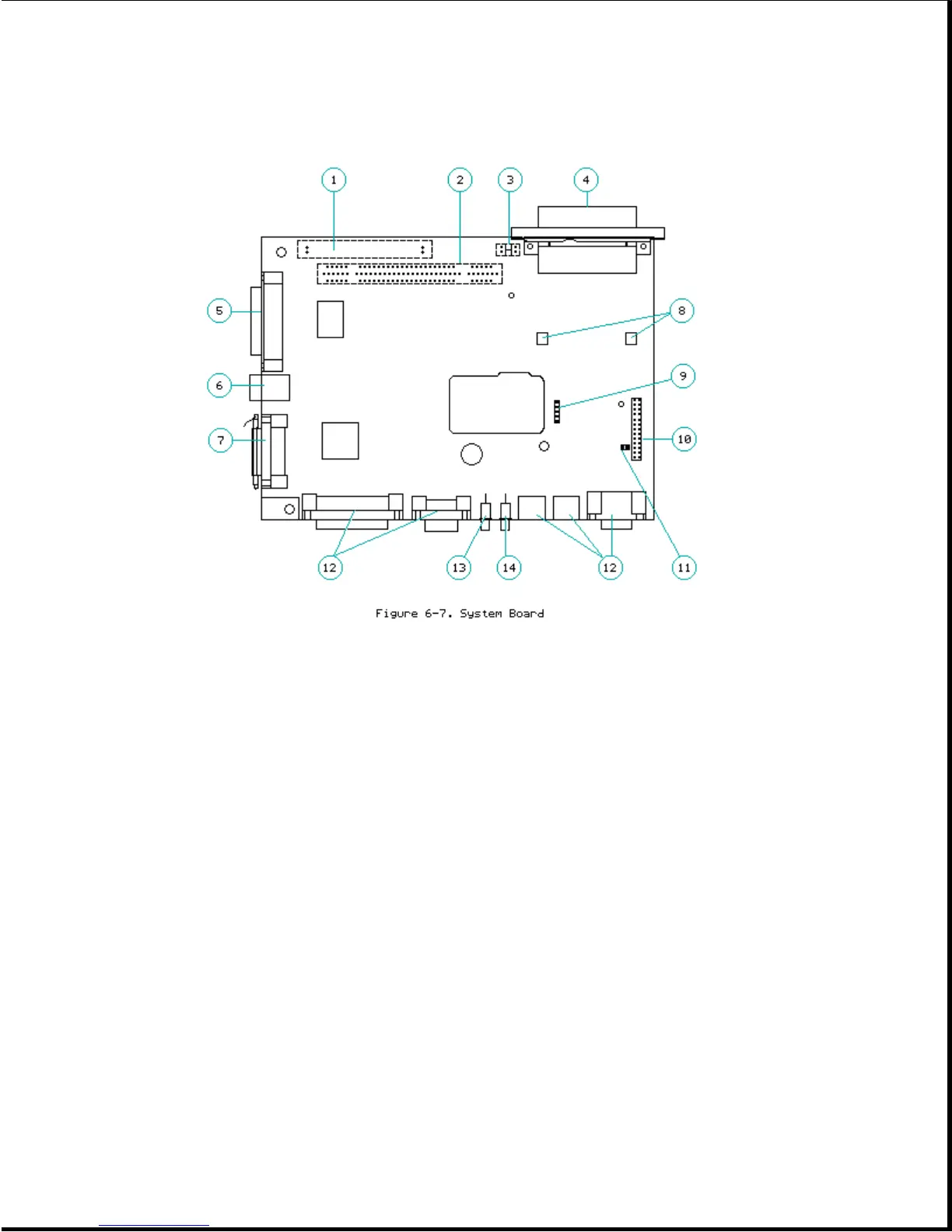
The following connectors, switches and sensors are on the system board
(Figure 6-7):
1. Internal SCSI-2 connector
2. Card edge connector for the vertical circuit board
3. Computer-present sensor
4. 198-pin external options connector for handling power and signal
information between the expansion base and computer
5. SCSI-2 connector
6. Ethernet RJ-45 connector
7. Ethernet AUI DB-15 connector
8. Motor position sensor
9. Connector for battery contacts board for the battery charger
10. Connector for the harness extension cable

Table of Contents

Questions and Answers:

Question and Answer IconNeed help?

Do you have a question about the Compaq LTE Elite and is the answer not in the manual?

Compaq LTE Elite Specifications

General IconGeneral
BrandCompaq
ModelLTE Elite
CategoryLaptop
LanguageEnglish

Related product manuals