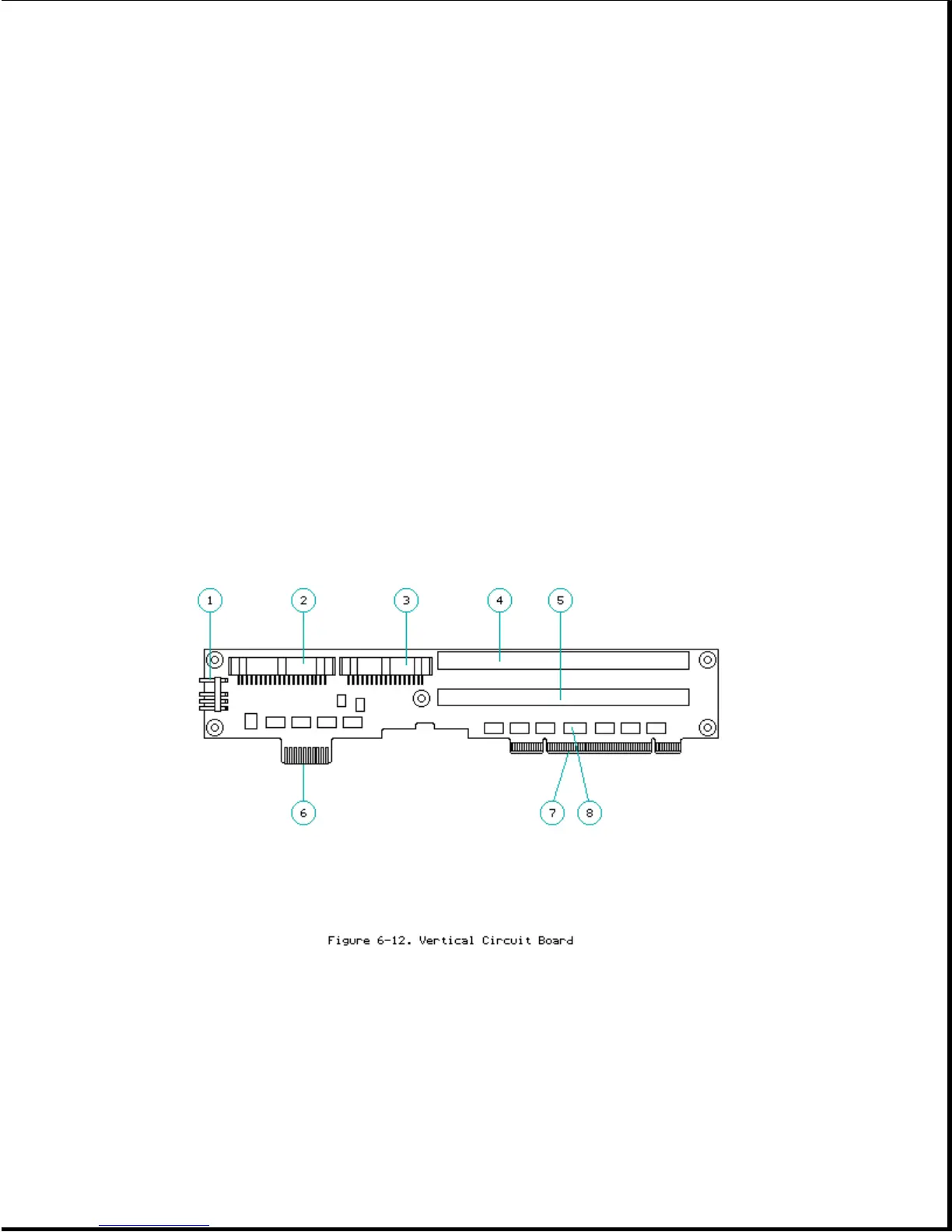
6. Edge card connection to the power supply
7. Edge card connector to the system board
8. Configuration switches for optional drives
In addition, the circuitry for the expansion base registers and hard drive
decode are on the vertical circuit board.
Configuration Switches
The configuration switches [8] (Figure 6-12) are accessible when the bottom
cover is removed. The configuration switch settings are listed on a label
on the bottom of the drive cage in drive position 1 (Figure 6-14). Refer to
Appendix C, "Configuring the System for Optional Drives in the Compaq
SmartStation", for more information on setting the configuration switches.
ISA Expansion Board Cage
The expansion board cage [1] attaches to the vertical circuit board [2]
(Figure 6-13). The expansion board cage accepts two full-size Industry
Standard Architecture (ISA) 8-/16-bit expansion slots [3], [4]. The slots
line up with two vertical through hole card edge connectors [5], [6] on the
vertical circuit board.