Technical Specifications
Table 4-10-8 terminal definition
Diagram
CTH2 PWM-04S1-EB expansion board suits for AC and DC charging guidance
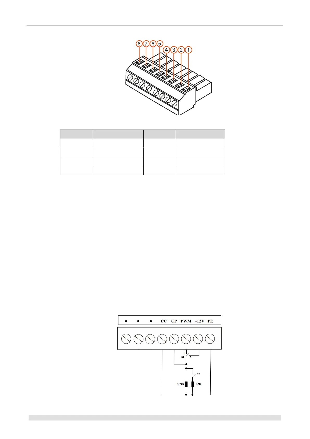
1) Diagram below shows the function of AC charging guidance:
+12V as the output port (1K resistance connected);
PWM output ±12V, pulse changeable PWM;
CC detect the status of cable connection (0X12--disconnected, 0X00--connected);
CP detect PWM output and connect +12V in spare time via switch S1;
PE refer to the earth
Wiring explanation:
When non-loaded, S1 switch to position 2, where CP will detect 12V, CP will detect the
output status (status value--0X01);
When the car connected, load 2.74K resistance, CP detect 9V in result in charging status 2
(status value--0X02);
Then switch S1 to position 1, output ± 9V PWM pulse changeable;
Finally close S2 to make 1.3K resistance and 2.74K in parallel, then the total resistance
external is about 1K, CP detect 6V PWM, in result in charging status 3(status value--0X03);
AC charging guidance diagram