CURTISS-WRIGHT 1
826448 VERSION 5 MARCH 2015 PROPRIETARY A-55
RTM EIA-232 Serial
Port Connectors
EIA-232 serial ports are available through RTM connectors, J2 and J3 (labelled as COM A and
COM B on the RTM connector panel). J2 connects to processor A's serial port, J3 to processor
B's serial port, The pinout for the serial ports is provided in Table A.38 below.
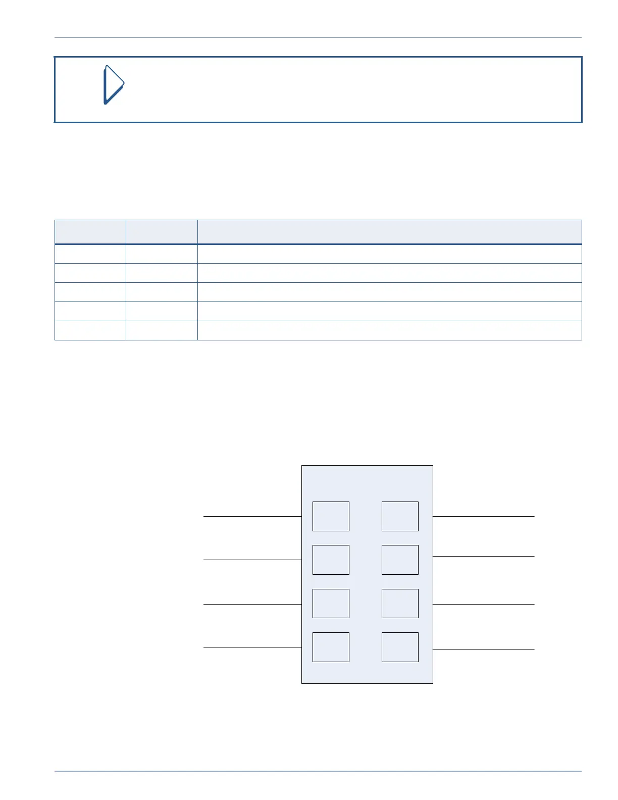
Serial Port Loopback Control
RTM Jumper block P3, which is shown in Figure A.20 below, allows any of the EIA-232 ports
to be put into loopback for testing purposes. Installing a jumper between transmit and receive
"loops" transmits data back to the receive data line.
Figure A.20: Serial Port Loopback Control via RTM P3
Serial ports are labelled consecutively. Ports 1-4 are EIA-232 and 5-6 are EIA-422.
Table A.38: RTM EIA-232 COM Ports A-D (J2-J3) Connector Details
Pin Number Signal Name Description
2 TX Data from processor UART
3 RX Data to processor UART
4 DTR/NC Connector J4: Data Terminal Ready signal (from PC)
5 GND signal ground
1, 6-9 NC these pins are not connected
NODE A0_TX
NODE A1_TX
NODE B0_TX
NODE B1_TX
NODE A0_RX
NODE A1_RX
NODE B0_RX
NODE B1_RX
Artisan Technology Group - Quality Instrumentation ... Guaranteed | (888) 88-SOURCE | www.artisantg.com