CHAMP-AV8 (VPX6-462) HARDWARE USER’S MANUAL CURTISS-WRIGHT
A-14 PROPRIETARY 826448 VERSION 5 MARCH 2015
BACKPLANE VPX CONNECTORS—DETAILED DESCRIPTION
The tables in this section show the mapping of CHAMP-AV8 signals to the VPX backplane
connectors.
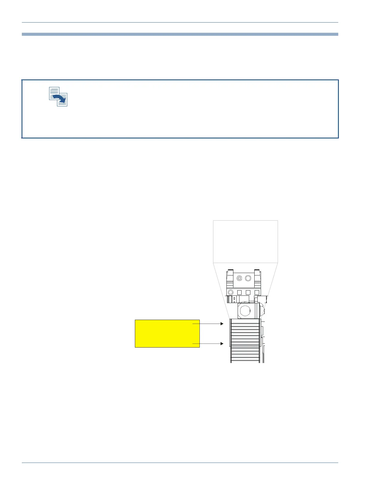
CHAMP-AV8 P0 UTILITY CONNECTOR PIN ASSIGNMENTS
The pinout tables are presented in the order of the rows when looking from the backplane,
(that is, i, h, g, f, e, d, c, b, a). Figure A.8 shows the location of the contacts on the
CHAMP-AV8 VITA 46 P0 Utility connector.
Figure A.8: CHAMP-AV8 P0 Utility Connector
Table A.3 and Table A.4 on page A-15 describe the signals that are available on the P0 Utility
connector on the CHAMP-AV8.
VPX is the name given to the family of VITA 46 standards available from:
http://www.VITA.com/
For detailed information describing the mapping of the 7-row VPX board connectors to the
9 row VPX backplane connectors, refer to section 7.6 “Backplane Pin Mappings” in
ANSI/VITA 46.0, VPX Baseline Standard, which is available for purchase from the above web
site.
VITA 46
Connector
Orientation:
i h g f e d c b a
P0 Wafer 1
to
P0 Wafer 8
Artisan Technology Group - Quality Instrumentation ... Guaranteed | (888) 88-SOURCE | www.artisantg.com