CURTISS-WRIGHT PRODUCT OVERVIEW
826448 VERSION 5 MARCH 2015 PROPRIETARY 1-37
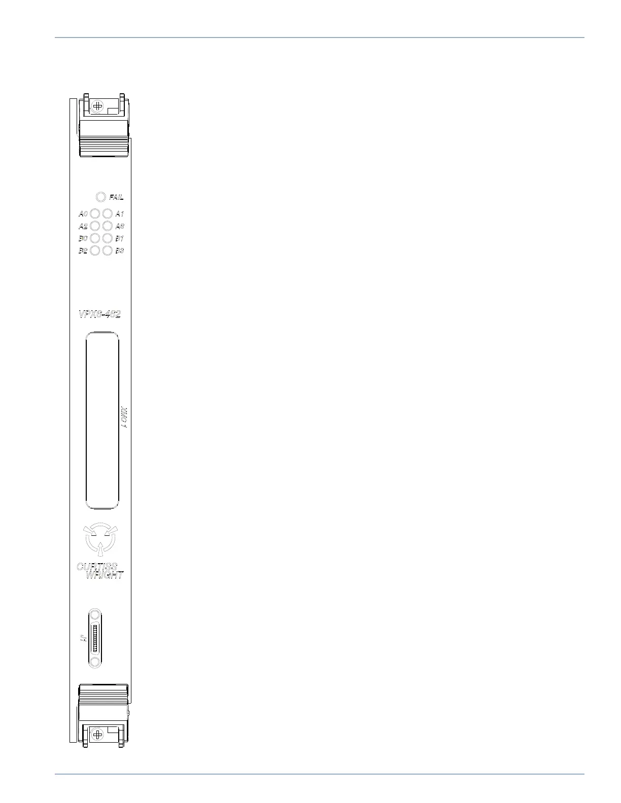
VPX6-462-A
Front Panel
An illustration showing the front panel that is mounted on the air-cooled version of the
CHAMP-AV8 (also known as the VPX6-462-A) is provided below, along with a brief description
of the indicators and connectors it provides.
Red FAIL LED: A red LED on the front panel is used to indicate a failure determined by the
on-board diagnostic firmware.
Processor Status LEDs A0, A1, A2, A3, B0, B1, B2, B3: Each of the processors has a
processor LED register that controls the green processor status LEDs seen opposite and two
of the surface mount status LEDs on the PWB.
XMC Slot: An opening is provided on the VPX6-462-A front panel to provide access to
connectors that may be incorporated on an optional XMC module that may be installed on the
basecard PWB. If there is no XMC module mounted, the opening is filled with a bezel.
J1 Connector: The J1 connector provides one EIA-232 serial interface and one GigE
interface (subject to build-time option) to each processor node. J1 also provides one USB
connection to the node A processor and supports a reset signal which when asserted resets
the entire card.
Artisan Technology Group - Quality Instrumentation ... Guaranteed | (888) 88-SOURCE | www.artisantg.com