CURTISS-WRIGHT PRE-INSTALLATION TASKS
826448 VERSION 5 MARCH 2015 PROPRIETARY 2-3
DETAILED POWER REQUIREMENTS
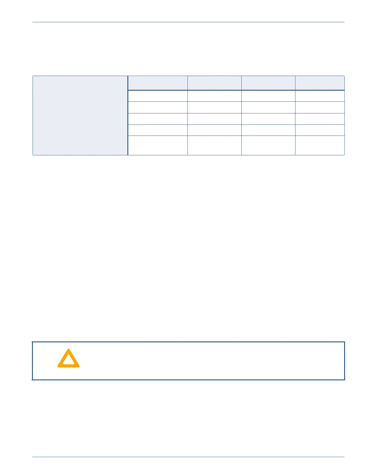
The CHAMP-AV8 requires +12 V and +3.3 V power supplies in order to operate. Table 2.1
shows the voltage and current requirements for the CHAMP-AV8.
Notes: 1. The ± 12V_AUX supplies are not used by the CHAMP-AV8 baseboard circuitry. How-
ever, they are routed to the XMC site on the board. Therefore the current drawn from
these supplies is XMC module-dependent.
2. VBAT is optional. VBAT sources current only when board is shutdown or main power is
“off”. When CPU is running, VBAT current is 0 Amps.
For proper operation of the CHAMP-AV8, the board must be installed in a VPX chassis that
meets the requirements of the following standards:
• VITA 46 Base Specification, ANSI/VITA 46.0-2007, 2007
• OpenVPX System Specification, ANSI/VITA 65-2010, 2010
The backplane voltages must meet all of the requirements specified in these documents.
Missing or below-level voltages will cause the power detection circuitry on the board to hold
the board in a powered down state. The power detection circuitry does not monitor the 12VAux
supplies since these power rails are used only to provide ±12V to the XMC site (no on-board
circuitry uses these voltages). When missing or below level backplane voltage other than
±12V causes the board to be is held in a powered down state, ±12V is not gated to the XMC
site, thereby also powering down the XMC.
In order to ensure proper operation of the CHAMP-AV8 board, the remote voltage sense lines
for the 12V and 3.3V power must be connected from the power supplies to the voltage rails
on the backplane. Chassis units (with built-in power supplies) furnished by most vendors
should already have these lines connected. However, if the chassis is powered from a user-
supplied power source, these lines must be connected. Consult the power supply user manual
if you have questions concerning the proper connection of these lines.
Table 2.1: Voltage and Current Requirements
Power Supply Requirements
(per ANSI/VITA 46.0–2007)
Mnemonic Description Nominal Value Tolerance
VS1, VS2 +12.0 VDC 12.0 V ±5%
3.3V_AUX +3.3 VDC 3.3 V ±5%
+12V_AUX
(see Note 1)
+12 VDC +12.0 V ±5%
-12V_AUX
(see Note 1)
-12 V -12.0 V ±5%
VBAT
(see Note 2)
Battery Backup +3V +2.7V (min)
+3.5V (max)
12 V and 3.3 V power must be supplied to the board through the VPX backplane.
The VPX chassis power supplies must be properly sized for the system and must utilize
remote backplane sensing to properly regulate the backplane voltages.
Artisan Technology Group - Quality Instrumentation ... Guaranteed | (888) 88-SOURCE | www.artisantg.com