1. Isolatecompressorpower.
2. RemovetheServiceSideCover.RefertoSection4.1.3.1ServiceSideCoverRemovalandInstallationon
page54.
3. WaitfortheLEDsontheBackplanetoturnoff.
4. RemovetheSerialDriver,BMCC,andPWM.
5. Setmultimeterforresistancechecks.
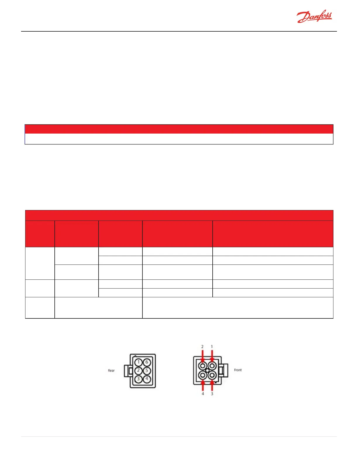
6. TestresistanceonbearingpowerfeedthroughpinsdefinedinTable4-45MagneticBearingCoil
ResistanceValues.RefertoFigure4-256FrontandRearBearingFeedthroughConnectorsforpin
locations.
• • • CAUTION • • •
Usecarenottodamagethepinswheninsertingtestleadsintotheconnectors.
7. ComparetheresistancevaluestothosedefinedinTable4-45MagneticBearingCoilResistanceValues.
8. Testinsulationofeachpintogroundandbetweencoils.
9. Iftheintegrityofthebearingpowerfeedthroughisinquestion,isolatethecompressor,recoverthe
refrigerantaccordingtoindustrystandards,removethefeedthroughandrepeattheabovesteps
directlyattheinternalbearingclusterblock.
Table 4-45 Magnetic Bearing Coil Resistance Values
Compressor Model & Design Sequence
Connector
Location
Bearing
Identification
Feedthrough
Pin
Identification
TTS300, TTS400, TGS230,
& TGS390
TTS350, TTS450, TTS500, TTS700, TGS310,
TGS380, TGH490, TGS520, TTH375, &
TGH285
RearBearing
Connector
RearRadialCoil
1&6 2.70-3.25Ω 2.70-3.25Ω
2&5 2.70-3.25Ω 2.70-3.25Ω
AxialCoil 3&4
5.70-6.20Ω(TTS300/TGS230only)
6.00-6.70Ω(TTS400/TGS390only)
6.00-6.70Ω
FrontBearing
Connector
FrontRadialCoil
1&2 2.70-3.25Ω 4.70-5.20Ω
3&4 2.70-3.25Ω 4.70-5.20Ω
Notes
RefertoFigure4-256FrontandRear
BearingFeedthroughConnectorsforpin
locations
Allresistancevaluesareinohms.Resistancetogroundandbetweencoilsshouldbe>100MΩ
@1KV
Figure 4-256 Front and Rear Bearing Feedthrough Connectors
M-SV-001-EN Rev. H-1/23/2023 Page 231 of 294

 Loading...


