8. DisconnecttheSCRManifoldSensorconnector.
9. LoosentheM5x16fastenersecuringtheIGVConnectorClampandrotatetheclampoutoftheway.
RefertoFigure4-26IGVConnectorClamp.
10. RemovetheharnessconnectorfromtheIGVFeedthrough.
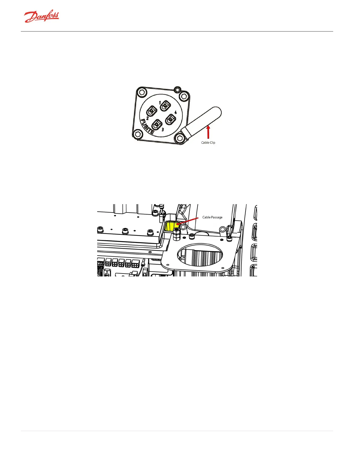
Figure 4-26 IGV Connector Clamp
11. Removethecableharnessinstagessothesameroutingcanbefollowedfortheinstallation.
Compressor Controller Cable Harness Installation
1. Routethecableharnessthroughtheholeinthemaincompressorhousingattheserviceside.Referto
Figure4-27CablePassage.
Figure 4-27 Cable Passage
2. RoutethecableharnessbetweentheDC-DCConverterandtheInverter.Laytheharnessoverthe
InverterPlate.
3. BendthecableharnessundertheMainsTerminalBlockandrouteittowardthecapacitorsideofthe
compressor.
4. InstalltheharnessontotheIGVFeedthrough.
5. RotatetheclampovertheIGVconnectorandtorquetheM5x16fastenerto25Nm(18ft.lb.)Referto
Figure4-26IGVConnectorClamp.
6. ConnecttheSCRManifoldSensorconnector(ifrequired).RefertoFigure4-23Pressure/Temperature
andSCRTemperatureSensorLocations-TTS300/TGS230onpage69andFigure4-25
Pressure/TemperatureSensorLocations-TTH375/TGH285onpage69forthisandthefollowingstep.
7. Connectthecablestothesuctionanddischargepressuresensors.
8. Insertthemoldedrubbergrommetinthenotchinthemaincompressorhousing.
9. Installthefour(4)Backplaneconnectors(J17,J18,J19,andJ21).
l
Pressure/temperaturesensorconnectors(J17,J18,andJ19)
l
IGVmotordriveconnector(J21)
Page 70 of 294 - M-SV-001-EN Rev. H 1/23/2023

 Loading...


