3.2 Terminal strip overview
3.2.1 Reference to Installation Instructions
Information about terminal strip overview and rear side controller view can be found in the "In-
stallation Instructions", which is located on DEIF's homepage under documentation for AGC
100.
3.3 Measurement systems
The AGC 100 is designed for measurement of voltages between 100 and 480V AC. For further reference, the
AC wiring diagrams are shown in the Installation Instructions. In menu 9130, the measurement principle can
be changed between three-phase, single phase and split phase.
Configure the AGC 100 to match the correct measuring system. When in doubt, contact the
switchboard manufacturer for information about the required adjustment.
The AGC 100 has four sets of nominal generator settings, which can be enabled individually in
the different measurement systems.
3.3.1 Single phase system
The single phase system consists of one phase and the neutral.
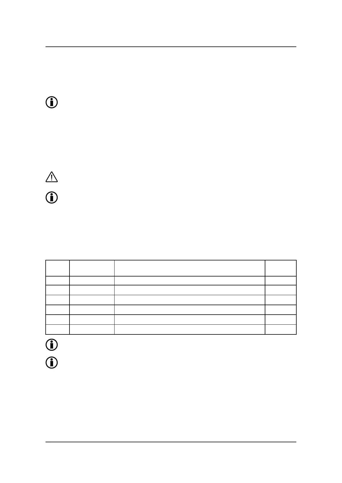
The following adjustments must be made to make the system ready for the single phase measuring (example
230V AC):
Setting Adjustment Description Adjust to
value
6004 G nom. voltage Phase-neutral voltage of the generator 230V AC
6041 G transformer Primary voltage of the G voltage transformer (if installed) U
NOM
x √3
6042 G transformer Secondary voltage of the G voltage transformer (if installed) U
NOM
x √3
6051 BB transformer Primary voltage of the BB voltage transformer (if installed) U
NOM
x √3
6052 BB transformer Secondary voltage of the BB voltage transformer (if installed) U
NOM
x √3
6053 BB nom. voltage Phase-phase voltage of the busbar U
NOM
x √3
The voltage alarms refer to U
NOM
(230V AC).
The AGC 100 has two sets of BB transformer settings, which can be enabled individually in this
measurement system.
3.3.2 Split phase system
This is a special application where two phases and neutral are connected to the AGC 100. The AGC 100
shows phases L1 and L3 in the display. The phase angle between L1 and L3 is 180 degrees. Split phase is
possible between L1-L2 or L1-L3.
AGC 100 Designer's Reference Handbook
4189340766 UK
Functional descriptions
DEIF A/S Page 12 of 152