AGC Designer’s Reference Handbook
DEIF A/S Page 59 of 168
View menu example
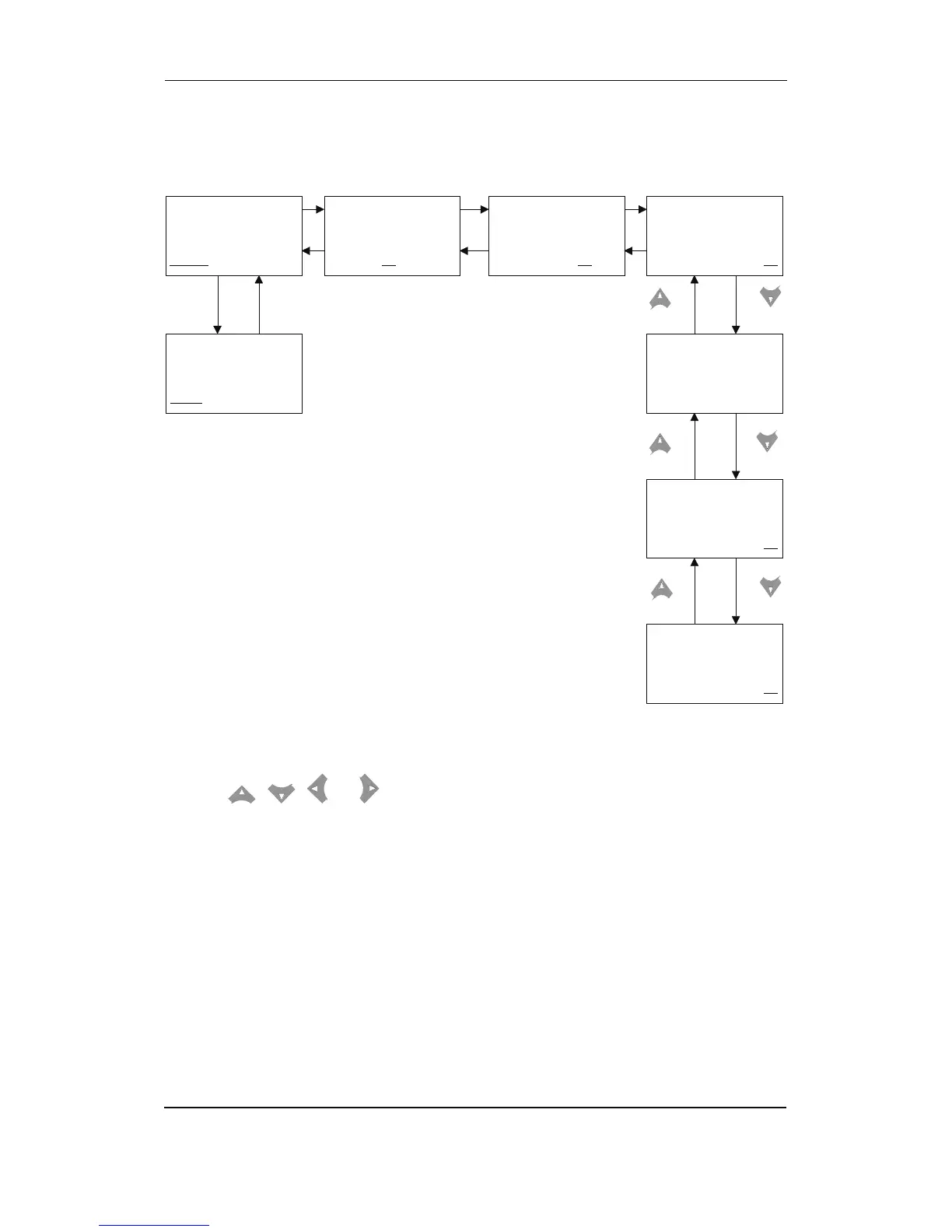
The following is an example of a configured view menu system. In this example 4 of 15 windows
have been configured in view 1.
ML 2- AGC V. 2.10.0
2004-12-01 09.35.54
SETUP
V3 V2 V1
G 440 438 440V
G-L1 50Hz 440V
B-L1 50Hz 440V
SETUP V3 V2 V1
MANUAL
B 440 438 440V
G 439 438 440V
SETUP V3
V2 V1
G 150 140 150A
B 440 438 440V
G 440 438 440V
SETUP V3 V2
V1
I-L1 150A
I-L2 140A
I-L3 150A
SETUP V3 V2 V1
G 150 140 150A
G 0.90PF 103KW
SETUP V3 V2 V1
U-SUPPLY 24V
SETUP V3 V2 V1
G 439 440 440V
f-L1 50.02Hz
PROTECTION SETUP
PROT
CTRL I/O SYST
BACKSEL
...Etc. (max. 15)
The menu navigating starts from the fourth display line in the entry window and is carried out
using the
, , and push-buttons.
The entry window displays view 3, (in the illustration above the window where ‘manual’ is
displayed).
Moving the cursor left or right offers the following possibilities.
• Setup menu – access to the following sub-menus:
- Protection setup
- Control setup
- I/O setup
- System setup
• View 3 – window displays operational status and selectable measurements
• View 2 – window displays selectable measurements
• View 1 – access to up to 15 selectable windows displaying selectable measurements