AGC Designer’s Reference Handbook
DEIF A/S Page 61 of 168
View line/second display line configuration
For generator For bus/mains For analogue input Communication/
other
V AC)
Current L2 (A) Tacho PID value #2.4
Current L3 (A) Voltage angle between L1-
L2 (deg.)
VDO 104 (pressure) PID value #2.5
Frequency/voltage L1 (Hz/V
AC)
VDO 105 (temperature) PID value #2.6
Frequency L1 (Hz) VDO 106 (fuel level) PID value #2.7
Frequency L2 (Hz) PID value #2.8
Frequency L3 (Hz)
Voltage angle between
generator voltage and bus
voltage (deg.)
Status line
Power factor/active power
(PF/kW)
Power supply voltage (V DC) Synchroscope
Active power (kW) Mains power (kW) Date and time
Reactive power/apparent
power
Negative voltage
(kVAr)/(kVA) Negative current
Reactive power (kVAr) Zero voltage
Apparent power (kVA) Zero current
Energy counter (kWh)
Power factor
Voltage angle between L1-
L2 (deg.)
Voltage angle between L2-
L3 (deg.)
Voltage angle between L3-
L1 (deg.)
Absolute run time (h)
Relative run time (h)
Next priority shift (h and
min.)
Fire run
Number of GB operations
Number of MB operations
Next service
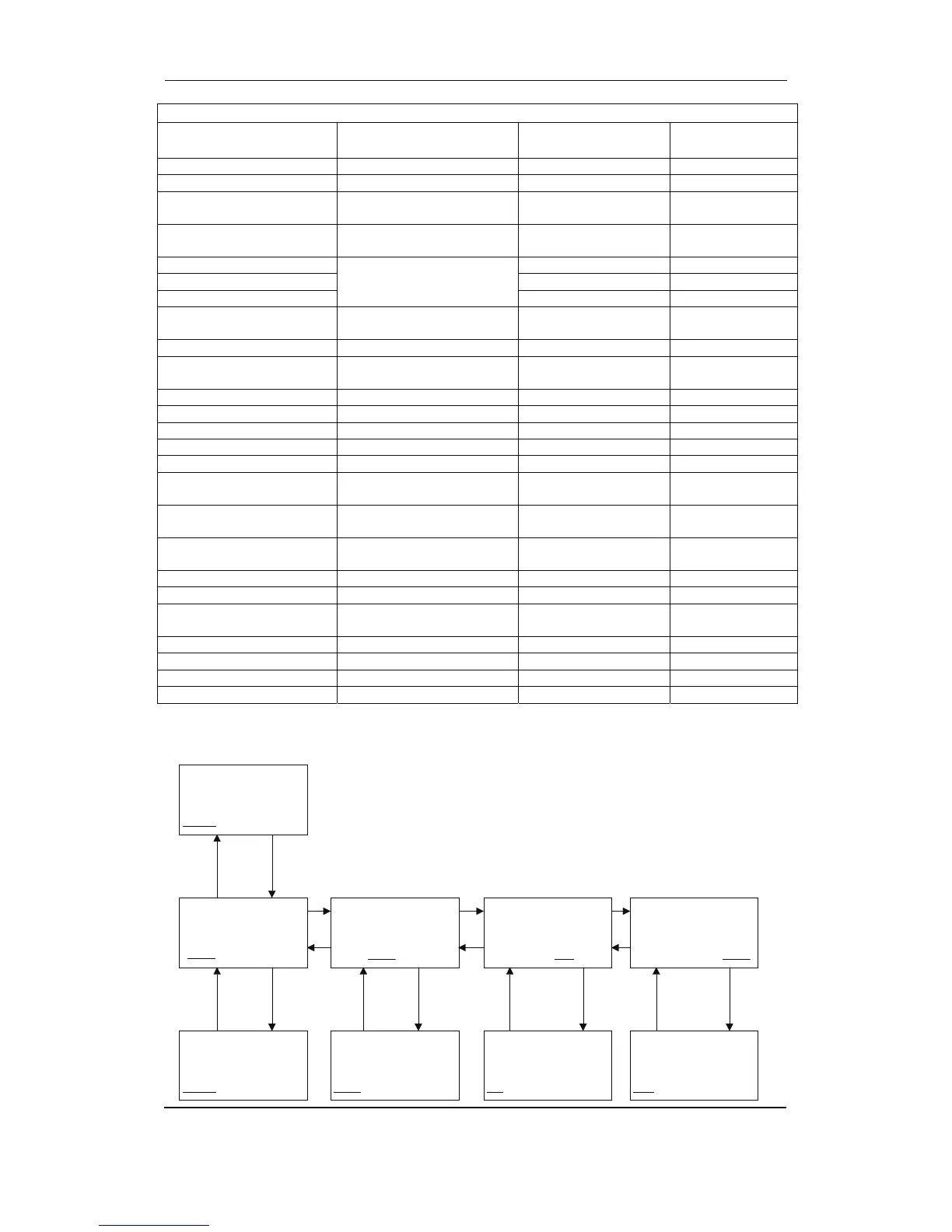
Setup structure
ML 2- AGC V. 2.10.0
2004-12-01 09.35.54
SETUP
V3 V2 V1
G 439 440 440V
f-L1 50.02Hz
PROTECTION SETUP
PROT
CTRL I/O SYST
G 439 440 440V
f-L1 50.02Hz
INPUT/OUTPUT SETUP
PROT CTRL I/O SYST
G 439 440 440V
f-L1 50.02Hz
SYSTEM SETUP
PROT CTRL I/O SYST
G 439 440 440V
f-L1 50.02Hz
CONT ROL SET UP
PROT CTRL I/O SYST
G 439 440 440V
PROTECTION SETUP
SET POINT 1 SETUP
PROT1
PROT2
G 439 440 440V
SYSTEM SETUP
GENERAL SET UP
GEN
MAINS COMM PM
G 439 440 440V
CONTROL SET UP
SYNCHRONICE SETUP
SYNC
REG
G 439 440 440V
INPUT/OUTPUT SETUP
BINARY INPUT SETUP
BIN
AIN OUT