Removing the controller card
Note: The base controller card is on the left, and the expansion controller card is on the right.
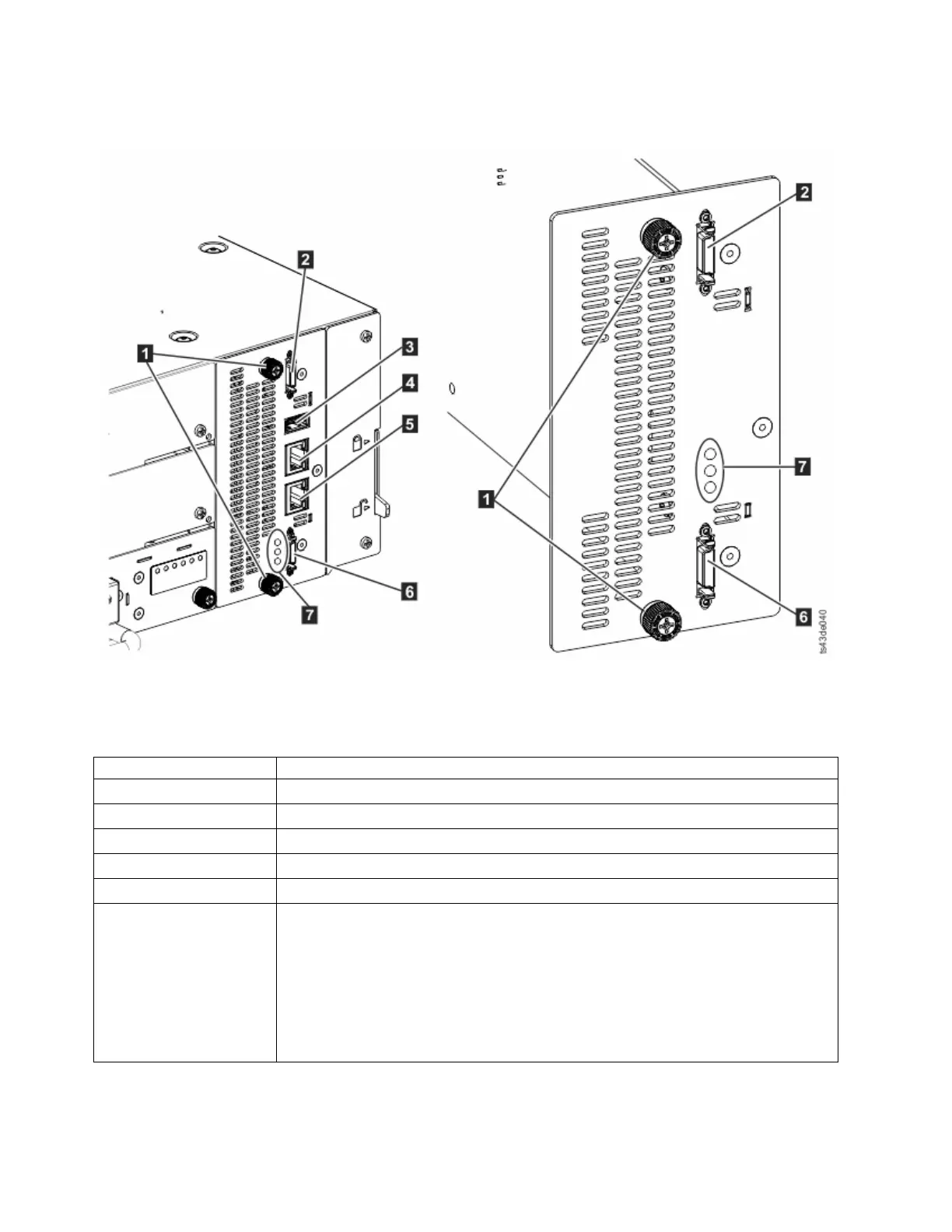
Table 44. Controller card components
▌1▐ Blue captive thumbscrews
▌2▐ Upper Expansion Module connection port
▌3▐ USB Port
▌4▐ Ethernet Port A
▌5▐ Ethernet Port B
▌6▐ Lower Expansion Module connection port
▌7▐ Controller card LEDs, top to bottom
v Green Controller Health Status. The flashing LED indicates that the controller is in
good health status and properly working.
v Yellow Controller Error. This LED turns on if the controller has a hardware issue. In
this case, the green LED stops flashing.
v Blue Unit Identifier. This LED is a beacon that can be turned on or off through the
Management GUI. The LED gives the user an indication that the controller needs
attention. See “Identifying a failed component” on page 73.
1. Unplug the AC power cables from the module that contains the failed controller card.
2. On the module that contains the failed controller card, remove the expansion interconnect cables (▌2▐
and ▌6▐) that connect to other modules, if present.
Figure 69. Controller card components
118 Dell EMC ML3 Tape Library: User's Guide