6-5
6
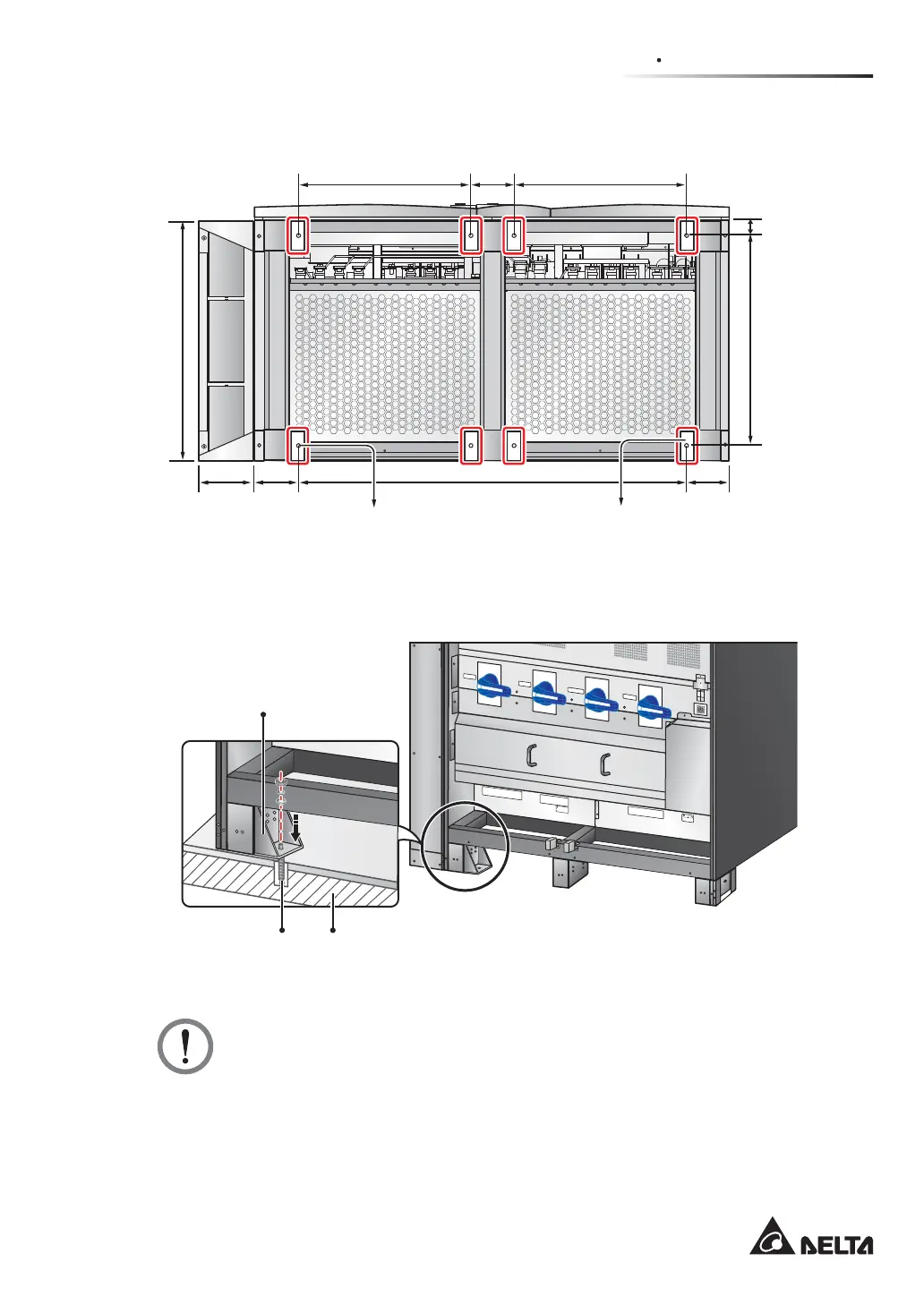
Top Cable Entry Cabinet
(Front of the UPS)
Balance
Supports
580.8 mm580.8 mm 145 mm
146.7 mm
50 mm 707.6 mm
816 mm
146.7 mm184 mm 1306.6 mm
(Rear of the UPS)
Mounting Hole
(Diameter: 13 mm)
(Figure 6-2: Mounting Hole Diagram)
T
S
R
N
U
P
S
O
U
T
P
U
T
NN
2
40
V
D
C
24
0
V
D
C
BA
TT
E
R
Y
I
N
P
U
T
T
S
R
N
A
C
I
N
P
U
T
R
S
T
B
Y
PA
S
S
I
N
P
U
T
OUTPUT SWITCH
MANUAL BYPASS SWITCH
BYPASS SWITCH
INPUT SWITCH
I
s
ol
a
t
e
Un
i
n
t
err
u
pt
i
bl
e
P
o
w
e
r
S
y
st
em
(UP
S
)
Th
e
n
che
ck
f
or
H
az
a
r
d
o
u
s
Voltag
e
b
e
t
ween a
ll
te
r
min
a
l
s
in
clu
d
in
g
t
h
e
p
r
o
t
e
ct
ive
eart
h
S
ee
in
stal
latio
n
i
nst
r
u
cti
o
n
s
b
e
f
o
r
e
c
o
n
n
e
c
t
in
g
t
o
the
sup
p
ly
A
p
p
aratet er
e
g
n
e
t
f
or
ti
lko
p
lin
g
t
il
et
I
T
f
o
rsy
n
ing
sn
e
tt
R
IS
K
O
F
V
O
LTAGE B
A
CKFEED
B
EFORE
W
O
RKIN
G ON THI
S
CI
RCU
I
T
(Front View)
Balance Support
Expansion Screw x 1 Ground
(Figure 6-3: Balance Support Installation)
WARNING:
There are eight balance supports locating at the front bottom and the rear bottom
of the UPS. If you don’t fix the eight balance supports on the ground, the UPS
PLJKWWRSSOHRYHU)RUVDIHW\FRQFHUQVSOHDVH¿[WKH836¶VEDODQFHVXSSRUWVRQ
the ground.