6-6
Ultron DPS Series
4
Remove the two panels shown in Figure 2-11 and follow 5.4 Wiring to perform wiring.
After wiring, reinstall the two panels.
5
To prevent possible damage from rodents, please take the provided six rodent shields
(including 22 M4 screws) out of the accessory package and install them on the UPS.
The provided rodent shields have four types, A, B, C and D. Each of type A and type B
has two pieces, and each of type C and type D has one piece.
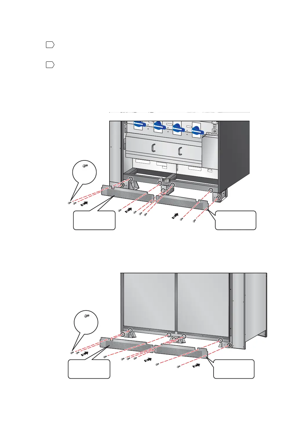
1. Follow Figure 6-4 to install a rodent shield A and a rodent shield B at the front
bottom of the UPS.
T
S
R
N
U
P
S
OU
T
P
U
T
NN
2
40
V
D
C
2
4
0
V
D
C
BA
TT
E
R
Y
IN
P
U
T
TS
R
N
AC
I
N
P
U
T
R
S
T
B
Y
PA
S
S
I
NP
UT
OUTPUT SWITCH
MA
NUA
L BYP
ASS
SW
I
TCH
BYPASS SWITCH
IN
PUT
SWI
TCH
Iso
l
at
e
Un
i
nt
e
r
r
u
p
t
i
bl
e
Po
w
e
r
Sy
s
t
em
(
U
PS)
The
n
c
heck f
o
r
Ha
z
a
r
d
o
u
s
V
o
l
t
a
g
e
betwe
e
n
a
l
l
ter
m
i
n
al
s
i
n
c
l
ud
i
n
g
t
he pr
o
tec
t
i
v
e
e
a
r
th
S
e
e
i
ns
tal
l
a
t
i
o
n
i
ns
t
r
u
c
t
i
ons
b
e
f
o
r
e
c
o
n
n
e
ctin
g
t
o
t
h
e
su
p
p
l
y
A
p
p
a
r
at
e
t
e
r
egnet fo
r
t
i
l
k
o
pli
n
g
t
i
l
e
t
IT
fo
r
s
yni
n
g
s
ne
t
t
RISK
OF VOLT
A
GE
B
ACKFEED
BEFOR
E
W
O
RKING O
N
TH
I
S
CI
RC
UI
T
(Front View)
M4
Screw
Rodent Shield A
(M4 Screw x 4)
Rodent Shield B
(M4 Screw x 4)
(Figure 6-4: Install the Rodent Shields A & B at the Front of the UPS)
2. Follow Figure 6-5 to install the other rodent shield A and the other rodent shield B
at the rear bottom of the UPS.
(Figure 6-5: Install the Rodent Shields A & B at the Rear of the UPS)
(Rear View)
M4
Screw
Rodent Shield A
(M4 Screw x 4)
Rodent Shield B
(M4 Screw x 4)