14
6.2 Interface Description
6.2.1 Fuse
Description: Main Fuse
Size: 2 A
Type: M2/250E, 20x5 mm Glasrohr
6.2.2 Voltage Supply
Description: GX2
Connector: Hirschmann STASEI 200
Voltage: 230/115 V, 50/60 Hz
6.2.3 Ethernet
Description: GX9
Connector: female connector RJ45
6.2.4 Screwdriver
Description: GX1
Connector: SUB-D 15-pole (socket)
6.2.5 I/O Interface
Description: GX6
Connector: SUB-D 25-pole (socket)
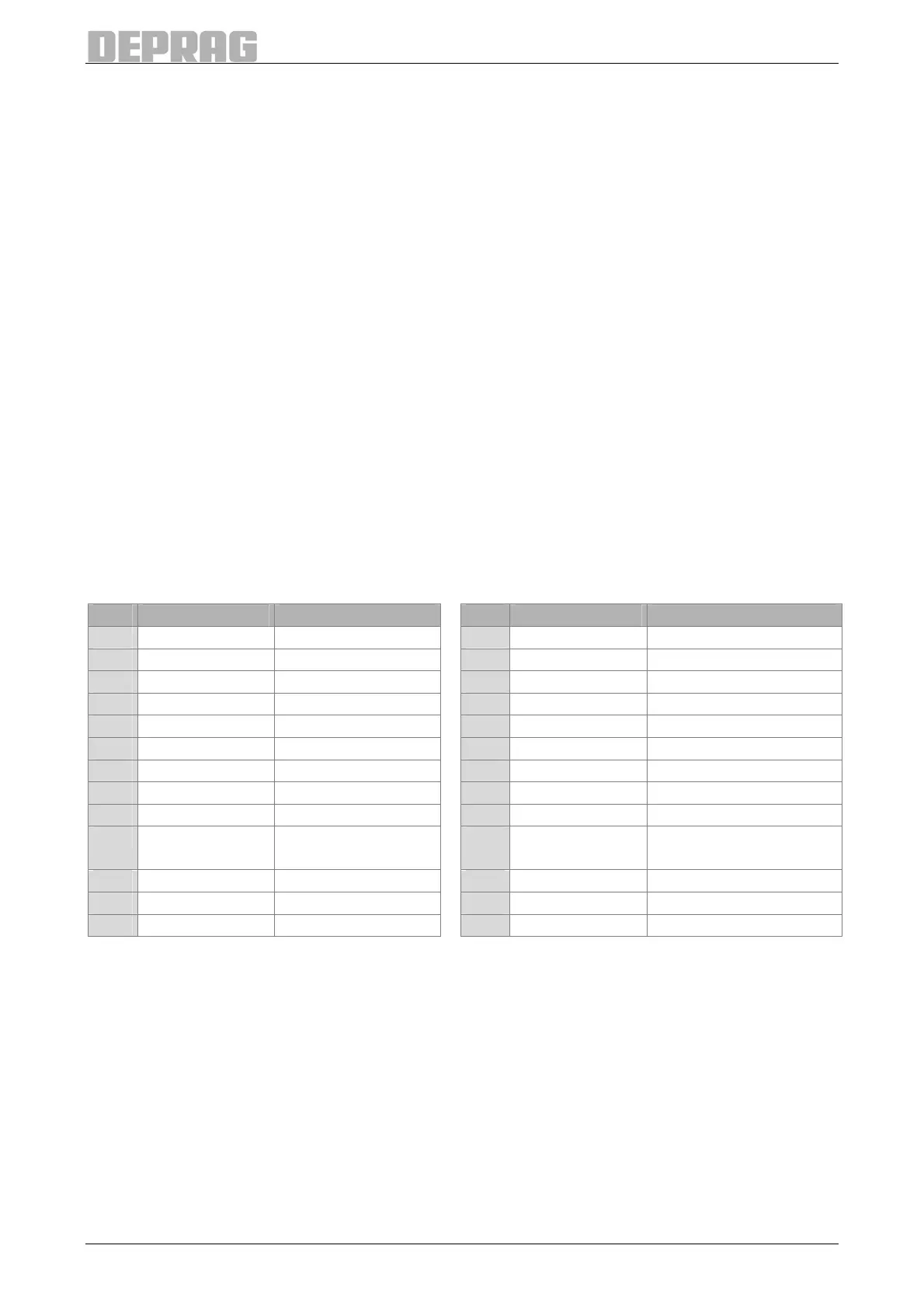
Pin Description Used for: Pin Description Used for:
1 Input 1 Start 14 Output 3 Screw Joint NOT O.K.
2 Input 2 -- 15 Output 4 ready
3 Input 3 Program Selection 16 Output 7 Change Part
4 Input 4 Program Selection 17 Output 8 --
5 Input 5 Program Selection 18 Input GND external
6 Input 6 Program Selection 19 Input 24 V external
7 Input 7 Reload 20 Output GND internal
8 Input 8 Start Release 21 Output 24 V internal
9 Input 9 External Stop 22 -- --
10 Input 11 Reset Error 23 Input Release controller /
emergency stop
11 Input 12 Release Part 24 Input n.c.
12 Output 1 System O.K. 25 -- --
13 Output 2 Screw Joint O.K.
Table 1: Pin assignment I/O interface
To use the I/O-ports the integrated I/O module of the AST11 has to be supplied with 24 V
DC. For this the following variants are permissible:
• Supply of the I/O module externally by pins 18 and 19
• Supply of the I/O module by the internal 24V of the AST11. To do this a contact has to
be built between pins 20 and 18, and between pins 21 and 19, respectively.
As a precondition to start a screwdriving program a 24 V signal has to be provided at input
'Release controller / emergency stop'. For this signal the internal voltage of the AST11 has
to be used. This can be done by a direct contact or by a relay controlled e. g. by a PLC
(pin 21 to pin 23, see drawing).

 Loading...
