24
7.6.2.2 Operation with a stationary Screwdriver
The start signal starts screw assembly on spindle screwdrivers. The program indicated in
the Setup "Type of program choice" menu is started.
• When “Inputs” is selected and a program is entered via the inputs of the I/O interface
then this program will be started (see 7.6.2.3 Selection and Start of a Screwdriving
Program via I/O interface).
• When “Fieldbus” is selected and a program is entered via the fieldbus then this pro-
gram will be started.
7.6.2.3 Selection and Start of a Screwdriving Program via I/O interface
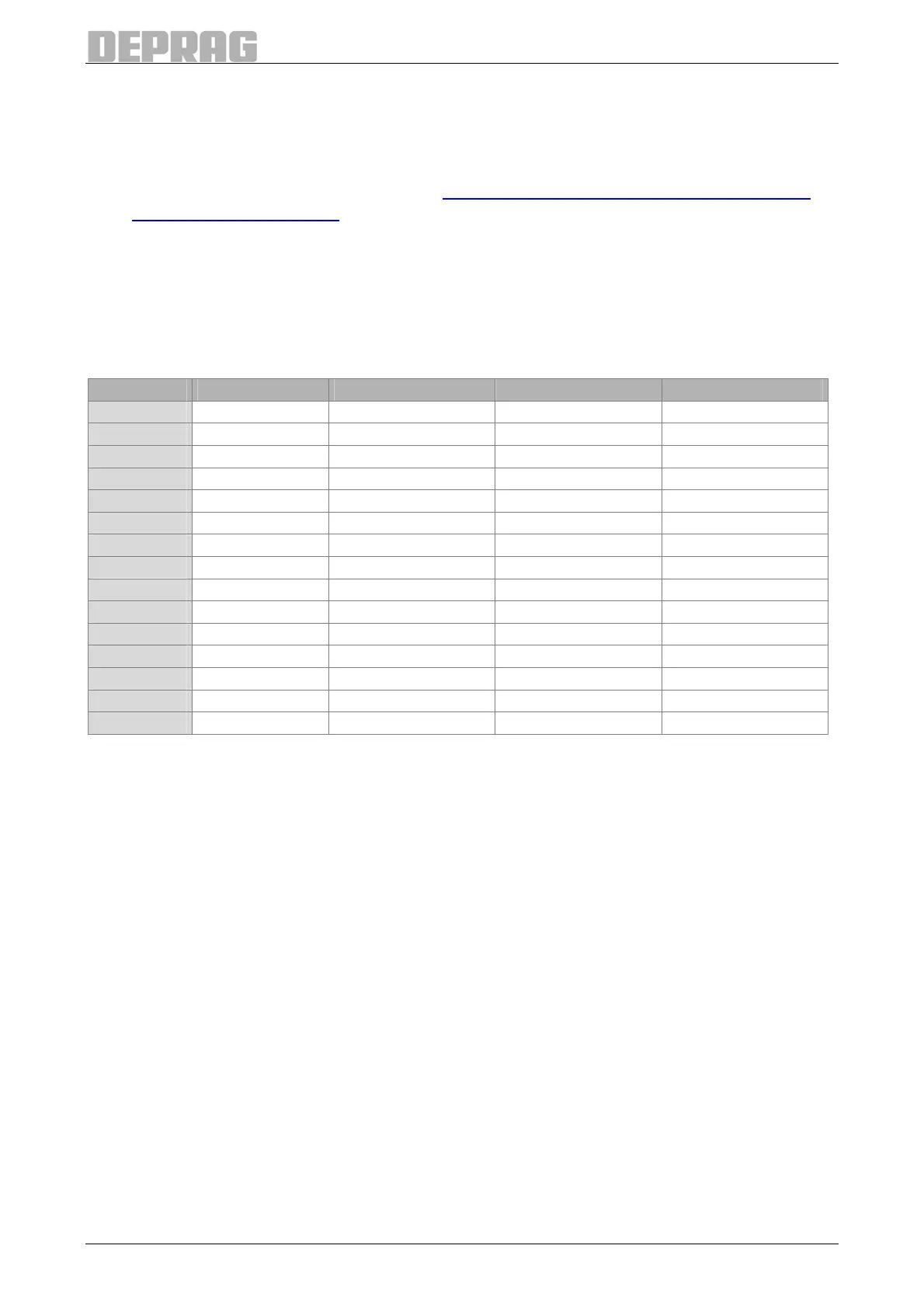
Use the inputs 3 to 6 of the I/O interface to select programs in accordance with the follow-
ing table:
Program Input 6 Input 5 Input 4 Input 3
1 0 0 0 1
2 0 0 1 0
3 0 0 1 1
4 0 1 0 0
5 0 1 0 1
6 0 1 1 0
7 0 1 1 1
8 1 0 0 0
9 1 0 0 1
10 1 0 1 0
11 1 0 1 1
12 1 1 0 0
13 1 1 0 1
14 1 1 1 0
15 1 1 1 1
Table 6: Program choice
7.6.2.4 Standard Communication higher level controller – AST11
Signal sequence of a screwdriving cycle:
Basic prerequisites:
• signal High to input ‘Release controller’ – pin 23
• presence of the program selection (may be present continuously, but it is evaluated
only when the start signal is applied)
Communication:
1. Indicator on output Ready, signal on HIGH? Sequence controller is ready for screw
assembly.
2. Enter signal HIGH on input program start
3. Indicator on output Ready, signal on LOW? Screw assembly has started.
4. Indicator on outputs OK and NOT OK, one of the signals on HIGH? Screw assembly
has finished.
5. Signal LOW on input program start, if required alter bit pattern for program pre-
selection
6. Wait for output Ready, signal on HIGH? Sequence controller is ready for screw assem-
bly again.
7. Continue according to item 1 – new screwdriving cycle

 Loading...
