29
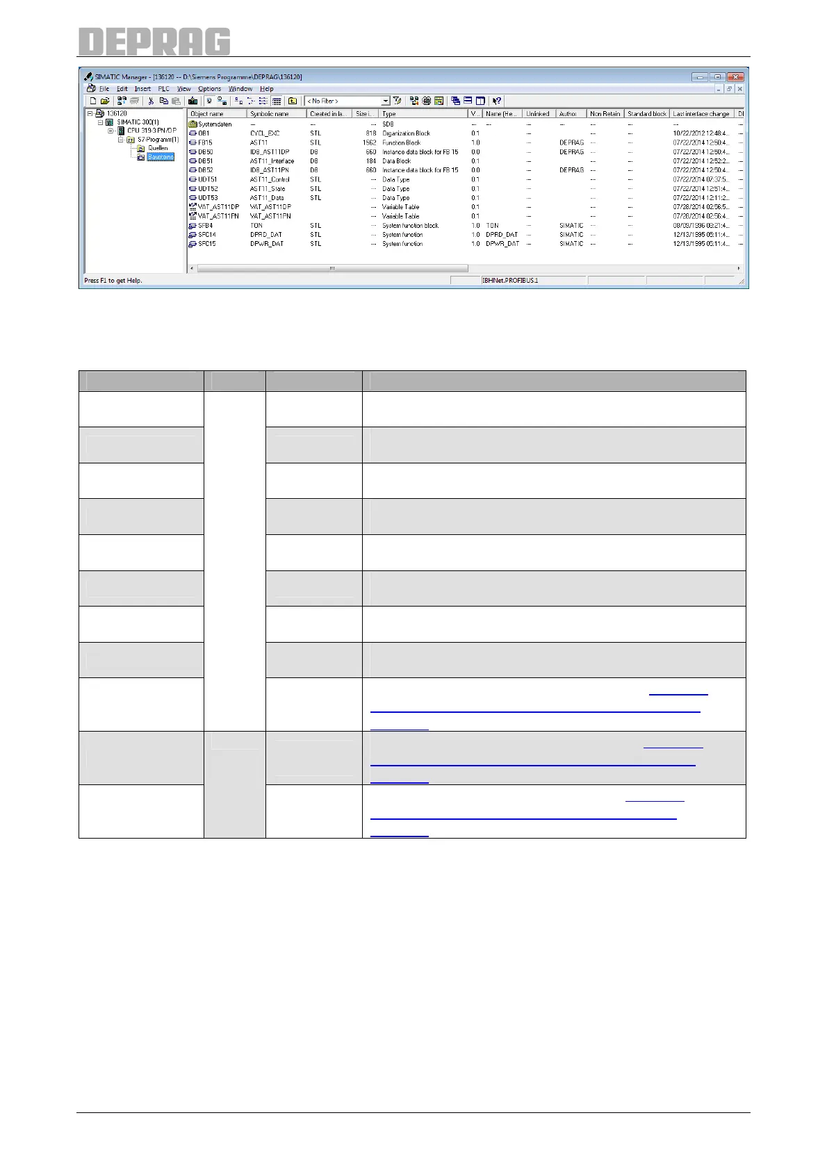
Table 8: Directory of the modules
7.7.1.3.1 Description - Interface parameters (FB15)
Designation Type Data type Description
I_Addr1 INT
Input address from the hardware configuration e.g.
256
I_Addr2 INT
Input address from the hardware configuration e.g.
320
I_Addr3 INT
Input address from the hardware configuration e.g.
384
I_Addr4 INT
Input address from the hardware configuration e.g.
448
O_Addr1 INT
Output address from the hardware configuration e.g.
256
O_Addr2 INT
Output address from the hardware configuration e.g.
320
O_Addr3 INT
Output address from the hardware configuration e.g.
384
O_Addr4 INT
Output address from the hardware configuration e.g.
448
Control
IN
Structure of
UDT 51
Data structure of the control signals (see 7.7.1.3.2
Description - Data structure of the control signals
(UDT51)
)
State
Structure of
UDT 52
Data structure of the status signals (see 7.7.1.3.3
Description - Data structure of the status signals
(UDT52))
Data
OUT
Structure of
UDT 53
Data structure of the screw data (see 7.7.1.3.5
Description - Data structure of the screw data
(UDT53)
)
Table 9: Description - Interface parameters (FB15)

 Loading...
