16
Port adjustment when used with barcode scanner:
• 9600 – 115200 baud selectable
• 5 – 8 data bits selectable
• 1 – 21 stop bits selectable
• parity selectable
• no protocol
6.2.7 Feeder Port
Description: GX8
Connector: Binder Round-Connector Series 763, M12-4pole
Color: black
Pin Description Used for:
1 Output GND
2 Output 24 V
3 Output 5 Reload
4 --
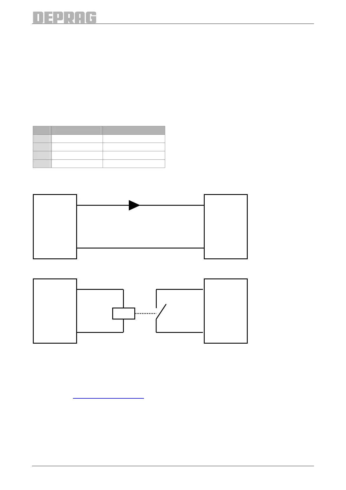
Table 3: Pin assignment feeder port
Potential connected:
Potential free:
Figure 4: Connection of feeder port
6.2.8 Emergency-Stop 2 Channel
The emergency stop 2 channel module is integrated as standard in the types 390041 B
and 390042 B. The AST11 types 390041 A and 390042 A can be converted to include this
module, see 17.9 Hardware-Module.
Description: GX11
Connector: Binder Round-Connector Series 763, M12-4pole (male)
Color: black
Pin 1
Pin 3
Output 5
GND GND
Input
AST11 Feeder
Pin 1
Pin 3
A1
A2
14
13
K1
Output 5
GND GND
Input
AST11 Feeder

 Loading...
