17
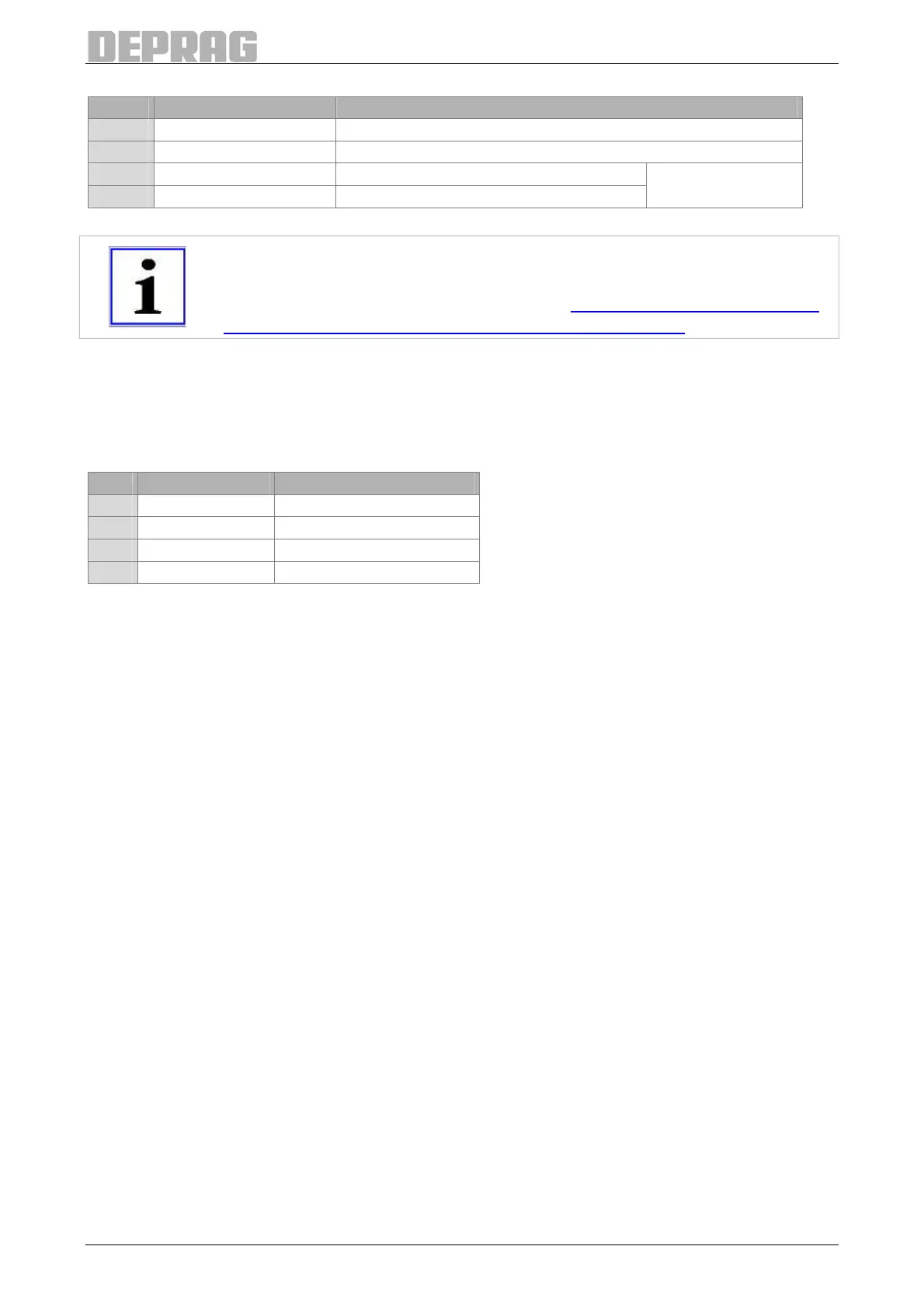
Pin Description Used for:
1 Contact Relay A1 (+24 V)
2 Contact Relay A2 (GND)
3 Contact Normally Closed Contact terminal 2
4 Contact Normally Closed Contact terminal 1
potential-free
contact
Table 4: Pin assignment emergency-stop 2 channel
IMPORTANT
The relay must only be switched on without any load!
Pay attention to the signal sequence (see 7.6.2.5 Standard Communica-
tion higher level controller – Emergency Stop 2 Channel) !
6.2.9 F-Controller Port
Description: GX7
Connector: Binder Round-Connector Series 763, M12-4pole
Color: red
Pin Description Used for
1 Output GND
2 Output 24 V
3 Output 6 Magnetic Valve
4 Input 10 Part Presence Sensor
Table 5: Pin assignment F-controller

 Loading...
