15
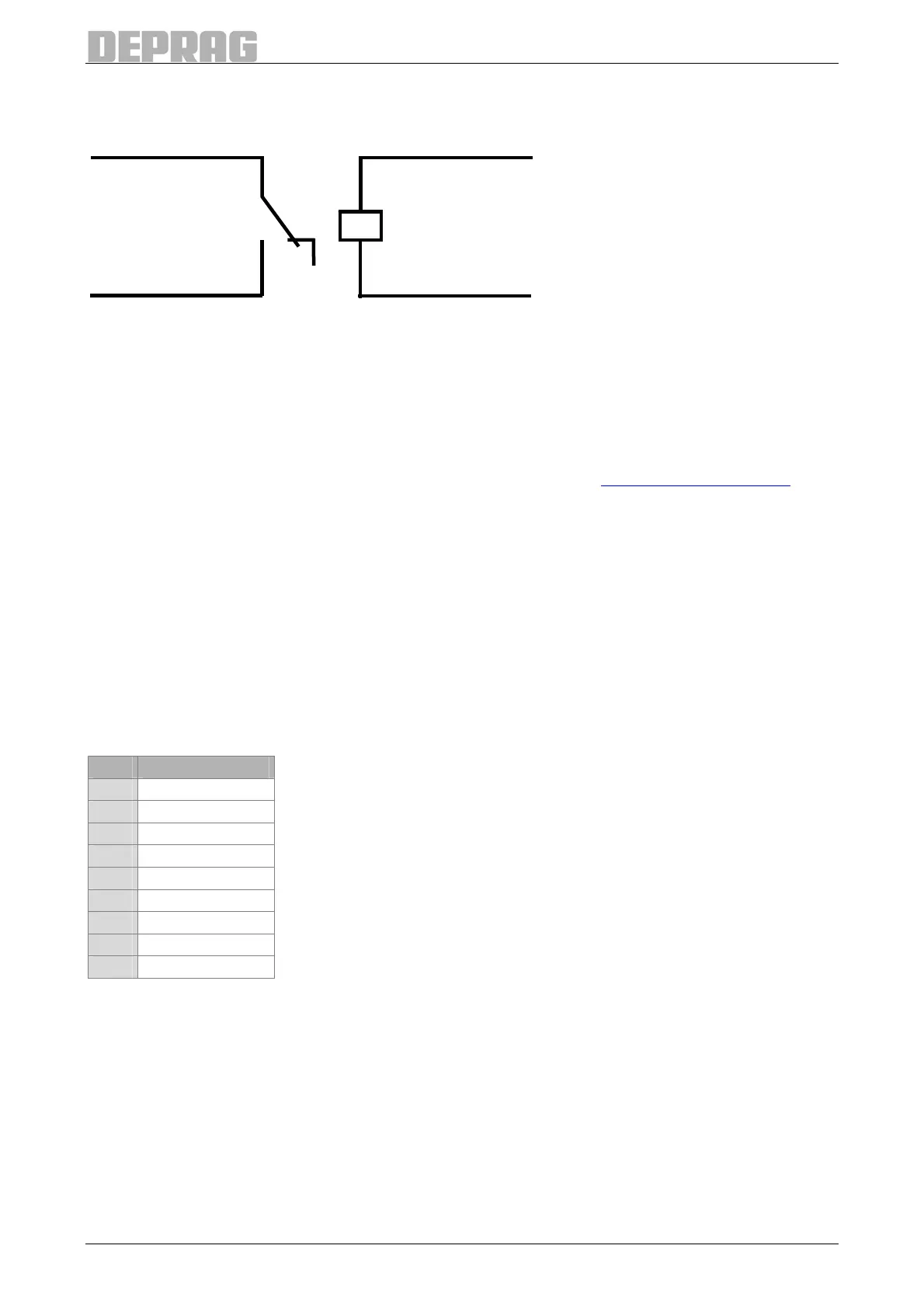
If a relay is used, when the sequence controller is switched on the signal 'Release control-
ler / emergency stop' must have a delay of at least 1 second after switching on the
115/230V supply. When an emergency-Stop has been activated, the signal has to be acti-
vated with a delay of at least 4 seconds.
When using hardware-module 385521 A (Safe torque off, see 17.9 Hardware-Module), the
internal voltage of the AST11 has to be provided permanently at input 'Release controller /
emergency stop' (contact pins 21 and 23).
6.2.6 Multifunctional Serial Interface
Description: GX10
Connector: SUB-D 9-pole (socket)
This interface can be used in conjunction with a printer as a serial printer interface, in com-
bination with an external fieldbus module as a fieldbus interface or in combination with a
barcode scanner.
Pin Description
1 --
2 TX
3 RX
4 --
5 GND
6 --
7 --
8 --
9 --
Table 2: Pin assignment multifunctional serial interface
Port adjustment when used as printer port:
• 9600 – 115200 baud selectable
• 8 data bits
• 1 stop bit
• no parity
• no protocol
Pin 21 internal 24 V
24 V (Emergency stop)
Pin 23 Release controller/
emergency stop
0 V

 Loading...
