2-6
95-8533
18.2
MAJOR COMPONENT
DESCRIPTIONS
The system has three main component groups
– the System Controller, LON (Local Operating
Network), and Intelligent Field Devices.
SYSTEM CONTROLLER
The Controller (see Figure 2-5) performs
all communication, command, and control
functions for the system. The Controller
supports both “Static” and “Programmable”
logic. Other features include:
• Redundant controller capability
• User pushbutton controls (reset,
acknowledge, etc.)
• “Real time” system clock
• Internal alarm sounder
• Vacuum fluorescent text based display that
shows current system status
• 8 programmable unsupervised inputs
• 8 programmable unsupervised relay
outputs
• RS-485 Modbus RTU communication
interface that supports coils, discrete
inputs, and holding registers
• Optional ControlNet communication board
supports redundant communication
channels.
• Optional EtherNet DLR communication
board supports EtherNet Device Level Ring
communications.
• Ethernet Interface Board supports
configuration, Modbus TCP/IP, controller
redundancy, and RS-485 Modbus.
• Serial Interface Board supports
configuration, RS-232 Modbus, controller
redundancy, and RS-485 Modbus.
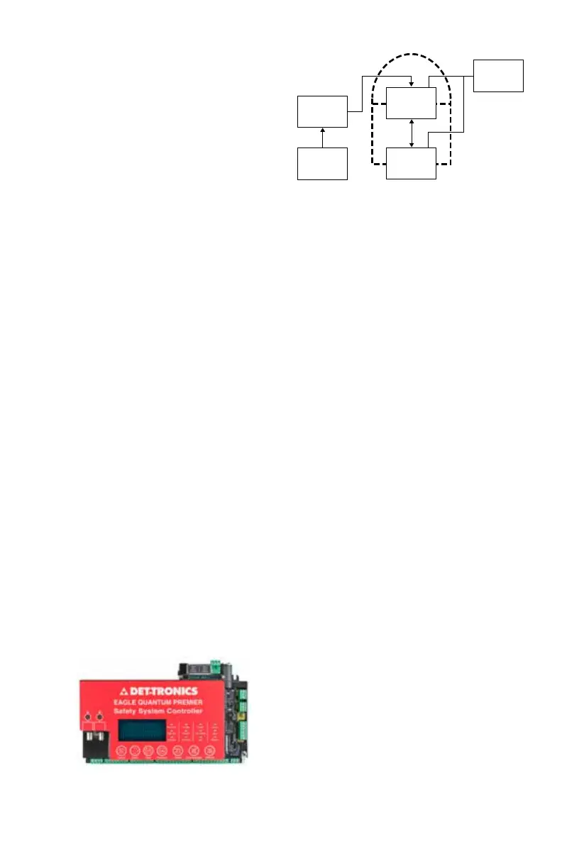
Controller Redundancy
The EQP controllers can be configured
as a redundant pair. See Figure 2-6. The
redundancy scheme is a hot standby system
that offers the following primary features:
• Automatic configuration of the standby
controller
• Bumpless transfer
• Forced and automatic switchover
• No downtime on controller replacement
• Automatic synchronization between
controllers
• Increased system availability
During normal operation one controller acts as
the “Master” while the other acts as the “Hot
Standby.”
Terminology used for redundancy:
Master controller This is the normal mode
for non-redundant and
master controllers. User
logic is executed, outputs
are being controlled and
all serial and/or Ethernet
ports are active.
Standby controller This controller is receiving
all inputs but does not
have any control over the
outputs and user logic is
not executed. The standby
controller receives
update information from
the master controller
to ensure a bumpless
transfer should a controller
switchover occur.
LON
S3
CONFIGURATION
SOFTWARE
ONE PROJECT FILE
LOADED TO
CONTROLLER A
CONTROLLER A
LON ADDRESS 1
CONTROLLER B
LON ADDRESS 2
DCS/PLC/HMI
HIGH SPEED
RS-232
SERIAL LINK
ETHERNET OR
RS-232
SERIAL LINK
ETHERNET
OR MODBUS
RS-485
B2275
Figure 2-6— Block Diagram of EQP System
with Redundant Controllers
Figure 2-5–System Controller