3-34
95-8533
18.2
WIRING
All electrical connections are made to the field
wiring connectors furnished with the module.
See Figure 3-37 for terminal identification.
Power Connector, Terminals 1 to 6
24 Vdc Power Input
Power connections to the DCIO depend upon
the total current consumption of all the channels
in the device. Each output-configured channel
can consume up to 2 amperes. Total output
current should be limited to 10 amperes.
Connect the power supply to terminals 1 and
2 or to terminals 4 and 5. Power wire shielding
should be connected to terminals 3 and 6.
1 — +
2 — –
3 — Shield*
4 — +
5 — –
6 — Shield*
*Shields on power wires are optional unless
required by local codes.
Supply
EDIO
Solenoid
VL
a
VL
b
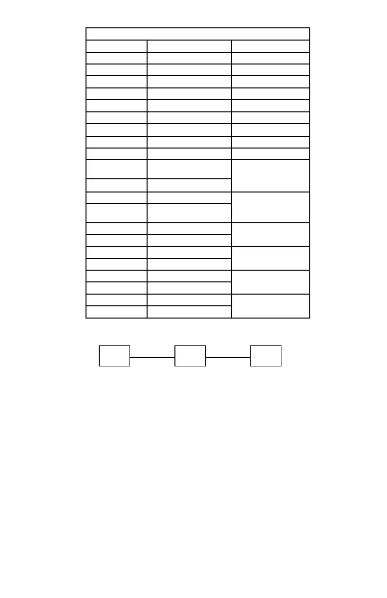
The following is based on EQ21xxPS (Primary Source) and Battery (Secondary Source)
Total wire voltage drop = 1.2 Vdc (MAX) = VL
a
+ VL
b
*
VL
a
= I
EDIO
x RL
a
I
EDIO
= Total current of EDIO and all active outputs
VL
b
= I
sol
x RL
b
I
sol
see Table 3-10
RL
a
& RL
b
= wire resistance = Ω per foot x 2 (x2 = B+ & B- wires)
Voltage Drop Voltage Drop
Figure 3-36—Field Wiring Distance Requirements for Solenoids
I
sol
Table 3-10
Manufacturer PN I
sol
(mAdc) @ 20.4 Vdc
Parker (Viking) 11591 NC 365
Parker (Viking) 11592 NC 365
Parker (Viking) 71395SN2ENJ1NOH111C2
340
Parker (Viking)
73218BN4UNLVNOC111C2
320
Parker (Viking) 73212BN4TNLVNOC322C2 600
Parker (Viking) 73212BN4TN00N0C111C2
330
ASCO RedHat
R8210A107
525
ASCO RedHat 8210A107
555
ASCO RedHat 8210G207
365
ASCO RedHat
Cat#
116 01
325
Viking PN
HV2740607 N.C.
Viking PN HV274608 N.C.
310
ASCO RedHat
Cat #
11602
Kidde-Fenwal 897494
130
Cat # 202-749-260563
Kidde-Fenwal 895630
1500
Cat # 81-895630-000
Kidde-Fenwal 890181
1500
Det-Tronics PN 00219-209
Ansul 570537
200
Macron
304.209.001
*Note: Alternate secondary power source when accept by Local AHJ, may increase permissible wire voltage drops. Actual
secondary voltage must be determined. Voltage and current at solenoid must be known and used in the equation.
Table 3-10—Typical Maximum Wire Length for FM Approved Solenoids for Deluge and Pre-Action Applications