95-8533
4-7
18.2
CONTROLNET STATUS INDICATORS
(Optional)
The optional ControlNet status indicator LEDs
function as follows: (see Table 4-3)
Steady - The indicator is on continuously in the
defined state.
Alternating - The two indicators alternate
between the two defined states at the same
time (applies to both indicators viewed
together). The two indicators are always in
opposite states, out of phase.
Flashing - The indicator alternates between
the two defined states (applies to each
indicator viewed independent of the other). If
both indicators are flashing, they must flash
together, in phase.
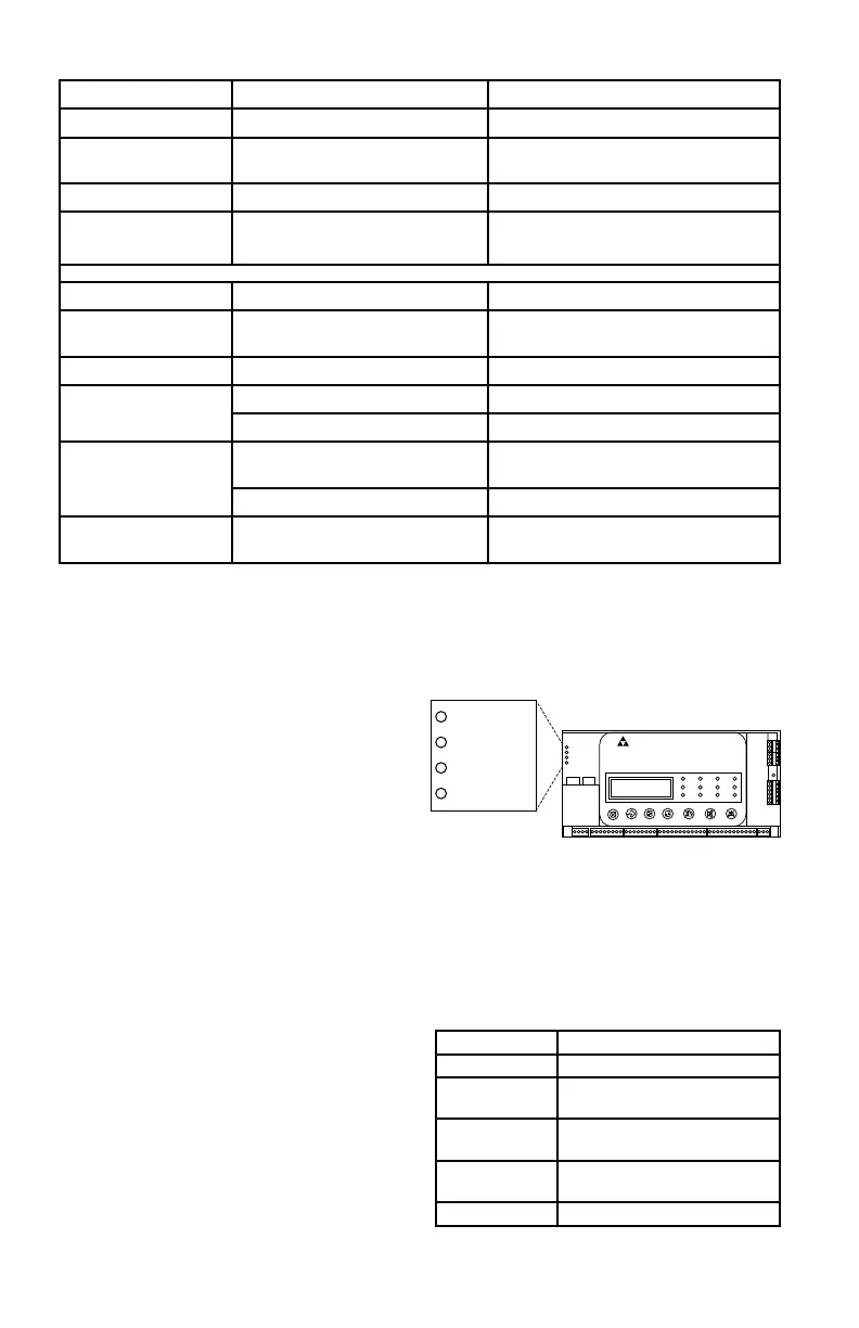
ETHERNET DLR STATUS INDICATORS
(Optional)
The EtherNet DLR has 4 status indicators:
Module Status, Network Status, Link Status 1
and Link Status 2. See Figure 4-5 for location.
The status indicator LEDs function as defined
in Tables 4-4 through 4-6. A test sequence is
performed on the Network Status and Module
Status LEDs during startup.
Table 4-3—Status of ControlNet LED Indicators
A and B Cause Action
Off No power None or power up.
Steady red Faulted unit Cycle power. If fault persists, contact
the factory.
Alternating red/green Self-test None
Alternating red/off Incorrect node configuration Check network address and other
ControlNet configuration parameters.
A or B Cause Action
Off Channel disabled Program network for redundant media,
if required.
Steady green Normal operation None
Flashing green/off Temporary errors None; unit will self-correct.
Listen only Cycle power.
Flashing red/off Media fault Check media for broken cables, loose
connectors,missing terminators, etc.
No other nodes present on network Add other nodes to the network.
Flashing red/green Incorrect network configuration Cycle power or reset unit. If fault
persists, contact the factory.
Figure 4-5—Location of EtherNet DLR Status LEDs
EAGLE QUANTUM PREMIER
Safety System Controller
Fire Alarm Inhibit Pow er
SuprHigh Gas
Trouble
Cntrl Flt
Lon Fault
Low Gas
Ack Silence
Out Inhibit
Eagle Quantum Premier
Time & Date
Cancel Enter Next Previous Reset Acknowledge Silence
DET-TRONICS
®
1 2
Module Status
Network Status
Link Status 1
Link Status 2
Module Status
Network Status
Link Status 1
Link Status 2
LED State Description
Off No power.
Green Controlled by a Scanner in
Run state.
Green, flashing Not configured, or Scanner in
idle state.
Red Major fault (EXCEPTION state,
FATAL error, etc.)
Red, flashing Recoverable fault(s)
Table 4-4—EtherNet DLR Module Status LED