3-46
95-8533
18.2
EQ22XXDCUEX DIGITAL COMMUNICA-
TION UNIT (USED WITH DET-TRONICS
COMBUSTIBLE GAS SENSORS)
Mounting
Determine the best mounting location for the
device. Whenever practical, the device should
be placed where it can easily be reached for
calibration.
IMPORTANT
Always orient the junction box with the
sensor pointing down.
WARNING
Do not apply power to the system with
the cover removed unless the area has
been veried to be free of combustible
gases or vapors.
Wiring
1. Remove the cover from the DCUEX.
CAUTION
ALWAYS discharge static from tools and
hands by touching the device body
before touching the communication
module or transmitter board.
2. Loosen the screws on the communication
module and remove it from the transmitter
board standoffs.
3. Disconnect the ribbon cable from the
communication module.
4. Remove the standoffs and detach the
transmitter board from the terminal wiring
board. Do not disconnect any wiring.
5. Connect all external wiring to the terminal
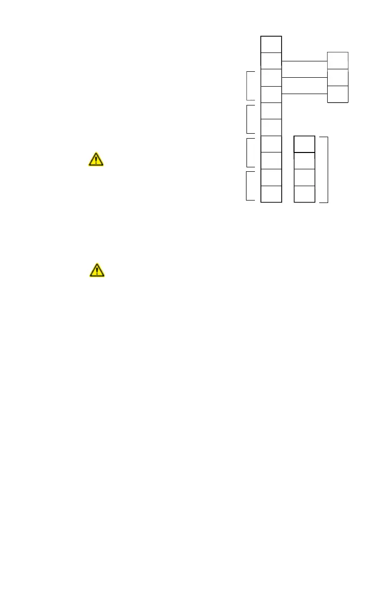
wiring board. (See Figure 3-54.)
NOTE
Make sure the ribbon cable is connected
to the terminal wiring board.
6. Attach the sensor to the device enclosure.
DO NOT overtighten.
NOTE
If a sensor separation kit is being used,
attach the sensor to the separation kit
junction box. (See Sensor Separation
with DCUEX below.)
7. Plug the sensor into P2 on the transmitter
board.
8. Mount the transmitter board to the
terminal wiring board and attach with the
standoffs.
NOTE
Be sure to note the correct orientation of
the transmitter board. If the transmitter
board is rotated 180° from proper
orientation, the device will not operate
correctly — a LON communication fault
will result. See Figure 3-57.
9. Plug the ribbon cable into the
communication module and re-attach it to
the transmitter board.
10. Set the device network address. (See
“Setting Device Network Addresses” in
this section.)
1
2
3
4
5
6
7
8
9
10
SIG
–
+
DCU TERMINAL BOARD DCU TRANSMITTER BOARD
(MIDDLE BOARD)
14
13
12
11
–
–
+
+
24 VDC
POINTWATCH CALIBRATE
4 TO 20 MA IN
–
+
A
B
A
B
SENSOR POWER
COM 2
COM SHIELD
COM 1
B1877
NOTES: 1 Catalytic Combustible Gas Sensor
Plugs into Connector Pins on the
Middle Board inside the Junction Box.
2 Connections Wired at the Factory.
2
2
2
Figure 3-54—DCU Transmitter Board Connected
to Terminal Wiring Board